Bride of Frankenstein - a cure for leftover parts cluttering the workshop.

Tanshanomi

Well-Known Member
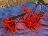
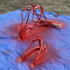
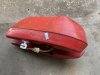
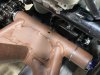
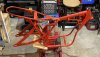
The weather was warm enough to lay a tarp in the yard and start painting the front wheel. I could only do one side at a time, and the weather is now turning cold, so it might be a while before I can finish it. However, what I did do looks very good.

Surface prep consisted of just scrubbing the wheel with soapy water and a white Scotchbrite pad. I left the tire on the rim and masked it off with blue painter’s tape, which is the exact wrong way to do it, but the result is as good as I dared hope. If the other side turns out similarly, I probably won’t bother with additional coats or buffing it.

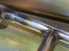
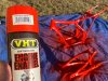
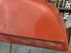
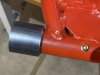
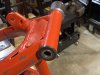
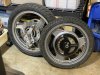
I popped the right-side hub cover on it just to get a visual impression, and I’m really pleased with my color choices. The Kawasaki Gentry Gray paint came from Custom Paints. It was the cheapest color-match option I found, and it turned out to be really good quality paint. It went on nicely and it’s an acceptably close match to the factory finish on the Ninja 500 back wheel. With the differences in the shapes of the spokes between the two wheels, matching paint is vital to making the wheels look somewhat like a matched set. When they’re mounted and 4-1/2 feet away from each other, they’ll look great.

IMG_5082-1024x768.jpg

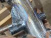
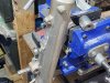
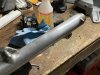
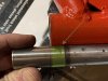
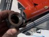
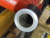
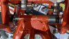
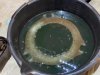
I also soaked the rusty front rotor in phosphoric acid. In this photo, it was just starting to react. I left it in for about 90 minutes. After a scrub and rub the braking surfaces looked good, but there was still some fluffy crud stuck inside the center passages. (Yes, inboard disk rotors were internally ventilated!)

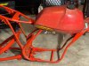
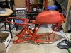
I’m getting excited about being able to reassemble things, but the frame requires more work first.

IMG_5083-1024x768.jpg
 
Last edited:

Tanshanomi

Well-Known Member
The modifications I’d made to The Bride’s frame had only been tack-welded in place with my little 110V flux-core welder. Before I could paint it, It needed structurally sound welds done by a pro. I dropped it off at the one-man welding shop down the street earlier this week, and he turned it around in 24 hours. I am very appreciative of having someone in the neighborhood who is willing to do piddly little jobs like this at a reasonable cost.

IMG_5258-1024x768.jpg IMG_5257-1024x768.jpg
 
Last edited:

Tanshanomi

Well-Known Member
I am struggling to decide whether to paint The Bride’s frame and swingarm to match the Can-Am Qualifier fuel tank, or go with basic black. I’m pretty conservative, and normally not a big fan of brightly colored frames. However, as haphazardly stuck together as this particular bike is, anything that could lend visual cohesiveness to it would be welcome. Decisions, decisions…

Bride-color-schemes.jpg
 

Tanshanomi

Well-Known Member
I like the red, and I wonder if your visual cohesion would also be improved if you colored the fenders
Unfortunately, the rear fender is a typical polypropylene enduro fender, and I have not not found paint that would adhere properly to the flexible plastic that comes in a color anywhere close to the tank's. I could do black, but I am not sure that would make any difference.
 

Tanshanomi

Well-Known Member
After weeks of waiting, we finally had of a sunny, calm, dry, sorta-warm (50° f) weekend afternoon. I took the opportunity to get a coat of paint on The Bride’s frame and swingarm.

6B984F0A-D6F2-4790-BA9E-8668EE9A8066.jpeg

After much deliberation, I went with “Chevrolet Orange-Red” engine paint. It’s the closest thing I could find to Can-Am Qualifier red without spending big money on custom-formulated paint. Frankly, there’s no guarantee the genuine factory color would match my oxidized, beat-up, 45-year-old plastic tank any better than this stuff, which is not only cheap but durable and readily available if I need to do modifications or touch-ups later.

0333C79B-3B33-4A1C-890E-172DDDD98333.jpeg

Once the enamel is good and hard, I’ll lightly sand this coat before hitting them with a second coat, flipped upside-down to catch the bottoms and the other spots I missed. The end result will have the gloss and attention to detail typical of a 1930s farm implement, but at least they won’t rust and will all be the same color.
 
Last edited:

Tanshanomi

Well-Known Member
While I’m waiting for the right weather to put a second coat on The Bride’s frame, I am keeping myself busy with miscellaneous tasks I can tackle in the meantime. This morning, I commenced removal of the vestigial brake caliper lugs on the Suzuki fork.

IMG_5438-1024x768.jpg
 

Tanshanomi

Well-Known Member
I plopped the tank on the frame to see exactly how badly the colors were mismatched. They're definitely different, but considering that the tank itself has about 10 different shades of "wrong," I find this acceptable.

A7EC35C7-3014-426E-8E5F-9F3A4DB6D911.jpeg
 

Tanshanomi

Well-Known Member
I’m almost to the point of putting The Bride back together.
Sunday afternoon, I got a second coat on the frame and swingarm.

IMG_5446-768x768.jpg

I also finished removing the unused lugs from the fork leg. It’s not flawless, but it’s a “20-footer,” which is within tolerance for the vehicle it’s going on. Rather than try to strip off the yellowed clear-coat and polish the whole thing, I am planning on shooting both fork lowers with a coat of “aluminum” finish silver paint.

IMG_5457-1024x768.jpg

I’m also attempting to clean up the fuel tank’s appearance, courtesy of acetone and a razor blade. It’ll never look great, but at least I can remove the dirt stains, chalky oxidization, and petrified decal adhesive. Some custom vinyl overlays would hide the permanently embossed “Can-Am” lettering.

IMG_5458-1024x768.jpg

The swingarm is not permanently installed yet. I just wanted to see how the swingarm and frame looked with matching paint. I need to do a few little things before I bolt them together permanently: install a zerk fitting, grease the bushings, and shorten the swingarm bolt slightly.

IMG_5459-1024x768.jpg
 

Tanshanomi

Well-Known Member
I spent more time working on The Bride’s fuel tank, and it’s coming along surprisingly well. I am following the technique demonstrated by TNT Moto on YouTube:


So far, I have sanded down the tank with a sanding sponge, then 400 grit sandpaper, then a quick test on one area with 800 and 1500. I then hit one corner with my heat gun, and I think it will look fairly decent.

IMG_5479-1024x768.jpg

The results aren't ideal, not only because I didn’t spend a great deal of time on it, but also because I didn’t have any 600 grit paper to do that important interim step with. There are some big gouges in the tank that I won’t be able to do anything about, but that doesn’t bother me. “Decent” is good enough.

I also bought some heavy-duty white adhesive vinyl sheet. I’ll add a contrasting color block on each side of the tank. They’ll not only cover up the embedded discoloration left behind by the Can-Am logo decals, but also help tie the tank to the white fenders visually.
 

Tanshanomi

Well-Known Member
Even though The Bride is being built out of salvage and cast-off parts, I’m genuinely attempting to engineer it properly and not half-ass anything. The swingarm bushings have been a nagging bit of half-assery that I was never comfortable with. As eager as I am to get the thing built, I decided there was no point in assembling a configuration I wasn’t confident in.

The issue results from my method of aligning the drive chain and rear wheel. To make room for the idler sprocket, I cut off a section of the swingarm pivot tube back in April of 2021. In order for the overall width to still match the inner pivot bushing, I simply added the part I cut off to the opposite side of the swingarm, along with a washer that was the same thickness of my hacksaw cut. I used three bushings: one on the left, one on the right with the flange removed and inserted into the swingarm itself, and a third one in the cut-off section that was now acting as a spacer.

a_016-4-1024x768.jpg

This had some undesirable consequences:
  • Load forces are moved towards the middle of the swingarm pivot bolt, farther away where the frame supports it. The 12mm pivot bolt the YZ125C swingarm uses is pretty wimpy to start with, so that’s no bueno.
  • The swingarm bushings are now closer together, so they have less mechanical leverage to resist torsional and side-loading forces on the road. The spacer with its third bushing really isn’t going to do anything to help distribute these loads. The YZ125C bushings are just impregnated delrin, so they might not be able to cope with heavier loading.
  • Perhaps most critically, I had to reduce the width of the pivot bushings on both side by about half. The right-side bushing had to be reduced because the swingarm tube has a step in the ID that prevented the bushing from going in all the way. On the left side, the stock bushing could be inserted fully, but since it is now located closer to the centerline of the bike, much of it was now located inboard of the inner bush’s bearing surface. The green area in the following picture shows how little overlap there is between the relocated swingarm and the inner bush.
IMG_5480-1024x768.jpg

So, plastic bushings that weren’t all that robust to start with now would now be asked to distribute higher torque loads over only half the area. This did not give me a warm fuzzy feeling.

The OD of the swingarm pivot is a few thou over 1.125″. I had purchased a length of heavy steel tubing with a 1-1/8″ ID back when I first started dealing with this problem, with a slightly vague idea of securely re-attaching the cut-off length of swingarm. However, since I assumed it would require welding, I put it on the “deal with later” list and continued with other project tasks. Well, now that I’m ready for final assembly, there is no “later.” As I was painting the swingarm, I was telling myself that the status quo would be “good enough.” I mean, it felt pretty solid. Yet, all the time, the half-ass detector in the back of my mind was flashing persistently.

I resolved to finally solve the problem properly. I could strip the paint and send the swingarm to my welding guy. But then I had another idea: once the two parts are installed, they’re held firmly together in the frame. A tight press fit and a longer bushing would distribute the loads just fine.

So, this morning, I drew up a diagram, chucked up a hunk of steel tube, and set out to fashion a sleeve. I took just a few thou off the ID and squared the face, then added a slight clearance taper on one side and a bit of chamfer on both openings.

IMG_5481-1024x768.jpg

I used my hydraulic press to press the cut-off portion into the sleeve. I then re-inserted the delrin bushings for alignment on the (full-width) inner bush and pressed the sleeve onto the swingarm. (No, I didn’t sand the paint off first. I told myself it would act as an extra filler and bonding agent.) The resulting bore actually ended up true!

IMG_5483-1024x768.jpg
IMG_5482-1024x768.jpg

The press operations crushed the flanges on the delrin bushes, but they were destined for the trash bin anyway. I ordered a bronze bush for the left side, which I will turn down slightly on one end to match the step in the frame tube; only about 3–5 thou will need to come off. For the right side, I found a 50mm long bushing, which will extend well beyond the joint between pressed-on section and the swingarm tube itself. It will take several weeks to get the new bushings, so this will slow down the project a bit, but at least once it goes together it will be whole-ass.
 

Tanshanomi

Well-Known Member
I ordered a selection of bushing stock and roller bearings off Ebay, in hopes of finding something that would suit my modified swingarm pivot. While I was waiting 1–2 weeks for $100+ worth of stuff to arrive, it occurred to me that I own a lathe. Why not fashion my own bushings from raw stock? I bought some 1.5″ diameter acetal copolymer rod off Amazon for $20, with next-day delivery. I did some measuring, sketched up my dimensions, and set to work.

IMG_5489-1024x768.jpg

I’d never turned acetal C before, but I had worked with HDPE and comparatively, this stuff is amazing. It machines just like alloy, except that you can make much bigger bites on each pass. Unlike HDPE, it doesn’t deflect or get mushy. I took it really slowly, creeping up on my numbers and test fitting for tolerances, because I wasn’t sure how much compression would play into the fit once it was pressed into the pivot tube.

IMG_5493-1024x768.jpg

I started with the left (drive) side, thinking that would be the easier of the two bushings to make, but it turned out to be somewehat problematic. My idea of extending the bushing beyond where the pivot tube ID had been machined for a bushing was a bigger issue than I thought. The tube had a pronounced welding seam inside, and even when that was removed, it was nowhere near round. I could press everything together, but the bush was obviously way off center at the other side of the swingarm. Hmmm. I then removed the flange from one of the original Yamaha bushes and pushed it into the other side of the swingarm as far as it would go. When I inserted the inner bearing sleeve, it wouldn’t turn at all. I eventually removed my homemade bush and filed down about a 60° section of the smaller OD until I got it to fit correctly.

IMG_5495-1024x768.jpg

The inner sleeve is now an easy slip fit all the way through and turns easily. My dial indicator measured between 0.001"–0.002" radial play, depending on where I positioned it. That's similar the original bushings and totally acceptable for a motorcycle with a 50 MPH top speed. I still need to finish the other side, of course. I plan to leave the original Yamaha bush where it is, and simply add a second, flanged outer bushing.

The pictures also show that my super-durable engine paint didn’t turn out to be so durable after all. The frame needs some touch-ups, and the whole swingarm will get a second coat of paint.
 
Last edited:

Tanshanomi

Well-Known Member
Last night, I turned my attention to the right side of the swingarm. The 18mm ID x 25mm OD bronze bushings I ordered had arrived. Out of the box, they were a beautiful slip-fit on the Yamaha inner bushing sleeve. So I pressed one of the bushings into the swingarm to see how well it might work. It was too tight, of course, but I measured how much the ID constricted, and it was a lot! (Between 0.020"–0.030".) And when I pressed it back out, the dimensions stayed compressed. So chucked it up and brought the ID back to spot on, then took a similar amount off the inside of another bronze bush. I pressed them both into the right side, one after the other, which which took up most of the depth available, and the outer one bridged the joint between the two sections. Individually, the clearance on both bushings felt perfect, but once the inner sleeve engaged all three bushings, it wouldn't turn easily. Fortunately, a couple of well-placed whacks on the pressed-on section with a hammer brought everything into alignment.

Since the bronze bushes aren't flanged, I still needed a spacer/thrust washer to fit over the last bit of inner sleeve length. I made a 0.1" thick disk out of the acetal-C. Once I sanded it down to about 0.095", that did the trick. It now butts up against a similar diameter spacer I made to fill the extra width between the swingarm and frame on the right side.

It was time to bolt it all together in the frame. It took me a couple attempts to remember where all the spacers and collars were supposed to go, but I got it all in place and...the swingarm could be wiggled, noticeably. WAAAA? Where was the play coming from? Did I make the poly bushing too sloppy? Was something compressible somewhere? Was—

Oh, wait. It helps if you cinch the swingarm bolt up tight. Ahhhhh. Perfect: It rotates easily with not a hint of wiggle.

IMG_5505-1024x576.jpg

One slight issue with this hybrid arrangement that you are not supposed to use grease around oil-impregnated bushings, but you are supposed to grease polymer bushings. I plan to just grease the left side bush liberally upon final assembly, and replace that zerk fitting in the middle with a 6mm button head screw, so I don't forget and do something stupid down the line.

Compared to the sketchy arrangement I had previously, I am much more confident in this configuration. It's now plenty robust. I'm glad I put in the extra work to get it right.
 
Last edited:

Tanshanomi

Well-Known Member
Just because I am a 12-year-old visual person, I took a few minutes to update my earlier, crude graphic mock-up of how I ultimately intend the Bride to look. It’s changed a lot over the course of the build process, so there’s no guarantee it won’t change between now and completion, but I like to have at least a general feel for it in my mind’s eye. I must admit, it doesn’t look much like I expected, but I like it!

Bride-color-scheme-final.jpg

Since it’s technically registered as a 1974 Panther DB175 but doesn’t look anything like one, I figured it probably should say “Panther” somewhere on it. So I designed this custom Panther logo for the sides of the tank:

Panther-logo-720x250.jpg
 
Top