Coleman BT200X

SAS289

Well-Known Member
#21
...
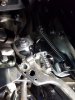
I was talking to my Dad about going to buy bolts for my engine mounts, "Oh I have some of those", he said.
I put them on, then took them off, I didn't use them as they were SAE, like you, I want to keep it metric.

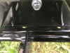
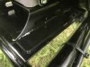
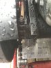
As far as the risers, I made my own, I hate drilling holes though, my bits always go dull before the first hole, perhaps I should discover the wonders of cutting fluid? So I just hacked holes in it with my angle grinder, quick and dirty, but functional.
That riser plate weighs much more than a couple 1" square tubing.

But I like to make my own sh...er crap if I can, everything is my own fault.
I agree and use what I have laying around in the garage. No shopping or ordering things. My engine riser is made of plastic. lol. During my build I made my own crankshaft holding tool and flywheel puller for my PVL flywheel, again with material I already had on hand.
 
#22
Sooooooo, I got a 3/4" crankshaft today, installed it and the TAV, bolted the engine to the riser plate and started to line it all up. All I can say is, "What a POS the rise plate is", with the rear tire and chain as straight as it can be, the riser plate bolt holes are about a half inch to the left of the original engine plate bolt holes. There's no way in hell I could shim the clutches out far enough for everything to line up, besides, I shouldn't have to, this was supposedly designed for this exact application. Here's some some pictures of just how crappy this thing really is, the first one is with the chain lined up, the second shows how far to the left the riser plate holes are and the third shows how far from the edge of the original engine plate the riser plate is.

IMG_2917.jpeg
IMG_2922.jpeg
IMG_2923.jpeg
 
#24
Sooooooo, I got a 3/4" crankshaft today, installed it and the TAV, bolted the engine to the riser plate and started to line it all up. All I can say is, "What a POS the rise plate is", with the rear tire and chain as straight as it can be, the riser plate bolt holes are about a half inch to the left of the original engine plate bolt holes. There's no way in hell I could shim the clutches out far enough for everything to line up, besides, I shouldn't have to, this was supposedly designed for this exact application. Here's some some pictures of just how crappy this thing really is, the first one is with the chain lined up, the second shows how far to the left the riser plate holes are and the third shows how far from the edge of the original engine plate the riser plate is.

View attachment 279686
View attachment 279687
View attachment 279688
But aren't the engine bolt holes lined up with the riser plate bolt holes?
 

SAS289

Well-Known Member
#25
But aren't the engine bolt holes lined up with the riser plate bolt holes?
They appear to be. I don't think it's riser issue. If anything it's the driver spacer or lack of spacing.

A TAV on a Coleman 200 is nothing new. Seeing the engine needing moved over that far, let alone needing moved over at all is a first for me. Prior to the release of this riser, everyone would just cut off the chain guard bracket and add whatever riser. There was no need to drill new mounting holes/slots in the engine plate to move the engine over.
 

mustangfrank

Well-Known Member
#28
Sooooooo, I got a 3/4" crankshaft today, installed it and the TAV, bolted the engine to the riser plate and started to line it all up. All I can say is, "What a POS the rise plate is", with the rear tire and chain as straight as it can be, the riser plate bolt holes are about a half inch to the left of the original engine plate bolt holes. There's no way in hell I could shim the clutches out far enough for everything to line up, besides, I shouldn't have to, this was supposedly designed for this exact application. Here's some some pictures of just how crappy this thing really is, the first one is with the chain lined up, the second shows how far to the left the riser plate holes are and the third shows how far from the edge of the original engine plate the riser plate is.

View attachment 279686
View attachment 279687
View attachment 279688
I don't doubt your skills but maybe start fresh with the riser & engine aligned in the factory holes and see if it can be aligned with the rear wheel/sprocket adjustment.
 
#29
Well, I got it to line up enough to be useable. The TAV must move the sprocket to the right more than the original, thus having to move the engine to the left. It is impossible to shim it enough and leave room on the crankshaft for the drive clutch if everything was perfect. Originally I had the engine bolted to the top of the riser plate with the bolts centered in their holes. I had to pull the engine all the way to the left on the riser plate and tighten it down, this bought me a little more than an 1/8" of an inch or so. Then I had to twist the riser plate to get the proper chain spacing between the TAV backing plate and driven pulley. I used two 14ga. machine bushings to space the outer driven pulley enough so the master link could pass through without interference. I then adjusted the right axle adjuster a bit more than the left and this got it lined up enough. The TAV sprocket is still canted, I'm sure everyones is, like everyone else who gets it lined up enough, call it good and be happy I guess. I did find that using an M6x12mm Phillips screw on the cooling tin leaves enough room for the TAV backing plate without grinding or removing the tins.

IMG_2913.jpeg
 
Last edited:
#30
Another bit of interesting information. I was watching a video of a TAV installation and the guy said he had to file the keyway groove in the sprocket in order for it to fit. I bought a TAV with a 7" driven pulley that I thought about using for this build but decided not to. On this setup, I used a 9 tooth front sprocket that had the key integrated into the sprocket and it fit the driven shaft but I had to shorten the key for the driven pulley. While messing with this setup, I grabbed the 10 tooth sprocket from the TAV kit that has the 7" driven pulley, much to my surprise the shaft and the keyway was bigger. Just like the Chinese clutches, it seems there's 16mm TAV units too. If you happen to need a variety of sprockets, it would be best to buy them from the same supplier.
 

SAS289

Well-Known Member
#31
Another bit of interesting information. I was watching a video of a TAV installation and the guy said he had to file the keyway groove in the sprocket in order for it to fit. I bought a TAV with a 7" driven pulley that I thought about using for this build but decided not to. On this setup, I used a 9 tooth front sprocket that had the key integrated into the sprocket and it fit the driven shaft but I had to shorten the key for the driven pulley. While messing with this setup, I grabbed the 10 tooth sprocket from the TAV kit that has the 7" driven pulley, much to my surprise the shaft and the keyway was bigger. Just like the Chinese clutches, it seems there's 16mm TAV units too. If you happen to need a variety of sprockets, it would be best to buy them from the same supplier.
Yes some TAV's come with a 16mm driven shaft. They use 5mm keys as opposed to the standard 3/16" key. It's too bad that you don't know what you're getting before you order. You want the 5/8" if you plan on changing sprockets.

For the best sprocket to engine alignment a straight edge should be used with the engine out. Measure using the engine plate/bolt slots as a reference. Some of us have found that the 200U axle slots are not even. The brake side needs adjusted further back for the best sprocket to engine alignment. Mine was around 1/8" difference from the sprocket side.

I like the 9/60 sprockets. But you have to be careful with the throttle.
 
#32
Yes some TAV's come with a 16mm driven shaft. They use 5mm keys as opposed to the standard 3/16" key. It's too bad that you don't know what you're getting before you order. You want the 5/8" if you plan on changing sprockets.

For the best sprocket to engine alignment a straight edge should be used with the engine out. Measure using the engine plate/bolt slots as a reference. Some of us have found that the 200U axle slots are not even. The brake side needs adjusted further back for the best sprocket to engine alignment. Mine was around 1/8" difference from the sprocket side.

I like the 9/60 sprockets. But you have to be careful with the throttle.
I use a laser crosshair for chain alignment, with a TAV the front sprocket is obstructed by the backing plate, with the engine out you can use the crosshairs on the rear sprocket and engine plate. The holes for the engine are 90° perpendicular to the back edge so if the rear sprocket is 90° perpendicular to the back edge of the engine plate, it will be perfectly aligned with the engine. That's why I was having this issue, I'm too precise for the poor alignment of the riser plate. One would think that if someone went through the trouble of designing one of these on a computer, it would at least be straight. Instead it seems that when they designed it, they didn't bother aligning the rear sprocket to the engine or engine plate first. Instead, everything has to be out of alignment just a bit for it all to work.
 
#33
Enough bitch'n and more riding, after getting it lined up enough to work the way it should, I will re-evaluate my score to be a 6-1/2 or 7 out of 10. The 20x7x8 knobby tires made a huge improvement, especially at the higher speeds. The stock tires would jar my kidneys over some of the rougher terrain, now, I just glide right over it. Although the tires aren't balanced that great, they were well worth the $70 for the pair. I took it out on the road and hit 37mph on my GPS. I didn't bypass the governor but I did grind off the tack weld on the throttle stop and installed a screw with a spring, now I can adjust the top end a bit if need be. I also moved the governor spring out to the hole in the middle of the arms bend. I haven't hooked up my tach yet but I'm fairly certain it's not getting close to the rev limit. Next up is a LED headlight and some pit bike foot pegs and I think that about wrap it up.
 

SAS289

Well-Known Member
#34
Enough bitch'n and more riding, after getting it lined up enough to work the way it should, I will re-evaluate my score to be a 6-1/2 or 7 out of 10. The 20x7x8 knobby tires made a huge improvement, especially at the higher speeds. The stock tires would jar my kidneys over some of the rougher terrain, now, I just glide right over it. Although the tires aren't balanced that great, they were well worth the $70 for the pair. I took it out on the road and hit 37mph on my GPS. I didn't bypass the governor but I did grind off the tack weld on the throttle stop and installed a screw with a spring, now I can adjust the top end a bit if need be. I also moved the governor spring out to the hole in the middle of the arms bend. I haven't hooked up my tach yet but I'm fairly certain it's not getting close to the rev limit. Next up is a LED headlight and some pit bike foot pegs and I think that about wrap it up.
37? I'm wondering what RPM you got it to?
 
#38
4k has exceeded the factory governor.
Before I hooked up the throttle cable, I ran the bike on jack stands to see if the governor would kick in with the spring being moved out so far. It did kick in and seemed like it was still below 5k, in fact it seemed to be the sweet spot, everything was smooth. After connecting the throttle with the stock return spring, the spring compresses and bottoms out before it even gets to that sweet spot. I'll have to find a spring the same length that has fewer coils and see what happens.
 

SAS289

Well-Known Member
#39
Before I hooked up the throttle cable, I ran the bike on jack stands to see if the governor would kick in with the spring being moved out so far. It did kick in and seemed like it was still below 5k, in fact it seemed to be the sweet spot, everything was smooth. After connecting the throttle with the stock return spring, the spring compresses and bottoms out before it even gets to that sweet spot. I'll have to find a spring the same length that has fewer coils and see what happens.
Or you can remove (cut) coils until the spring doesn't bind as much. I cut mine down to the point of the spring being completely relaxed in the idle position. Then I added the familiar return spring that the Colemans do not come with.

20170703_182437.jpg
 
#40
I think we all can agree that the whole point of the riser plate is to install a TAV on a Coleman mini bike, correct?. If you don't want to cut the hoop off the frame, the engine has to be raised and shifted forward approximately 1-1/2". What wasn't taken into consideration was, is the front sprocket going to be in the same location as the original after installing the TAV, the answer is NO!. For those who think I'm the only one with the alignment issue, here's some pictures of a stock setup and after the TAV is installed. Measuring from the back of the backing plate to the center of the sprocket on each setup, the front sprocket on the TAV is 3/8" of an inch further to the right. I use the back of the backing plate because with the engine in the same location (left/right) the back of the backing plate will also be in the same location (a known constant). The only variable is the front sprocket. There's no way one could shim the sprocket 3/8" more and still have enough room on the driven pulley shaft. The best way to design the riser plate would have been to make a jig keeping the front sprocket in it's original location, then install the TAV so the front sprocket is in the same location then measuring where the engine has to be located from there, not just lift and shift forward. Or do like I did, align the rear sprocket 90° perpendicular to the back of the original engine plate using a laser crosshair. This way the rear axle is in perfect alignment with the drive unit, then install the TAV on the engine and adjust it left/right until the front sprocket is centered with the rear sprocket.

IMG_2951.jpeg
IMG_2933.jpeg
 
Last edited:
Top