Dr. Shop Teacher's JFF Gilson Knight Rider

#1
Thanks to Mr. Pat and Cheezy for hosting the Build-off once again--you two do this with just the right amount of patience and humor. I'll not be posting questions as to my fitment on the bike as I know this one fits.:laugh: I look forward to seeing all the craftsmanship exhibited by the entrants, let's have some fun!

Since I started on this Gilson in the fall but really haven't got too far, I thought I'd move it over to the build-off. Here's my entry photo:
 
#9
Ah....another informative well documented Dr Shop Teacher build. Love these Gilson! Can’t wait to see more...[emoji1303]


Sent from my iPhone using Tapatalk
 
#10
I like it :)
I have a couple Gilson/Wards 525 bikes I haven't entered yet. I'll enter opnce I find time to take pictures. I have 2 Rupps too. Last year I built 4 and this year I'll try 4 again. Yes - I'm crazy :)
Danford1
 
#14
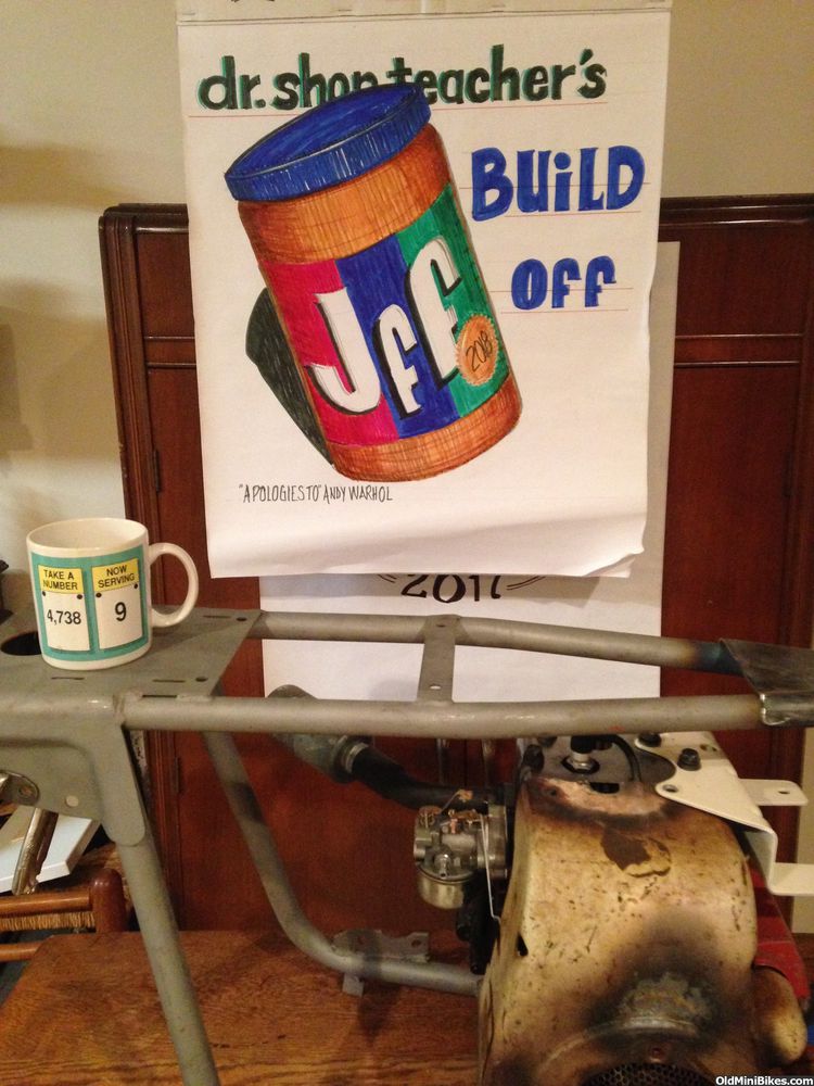
Let's go modeling! #1

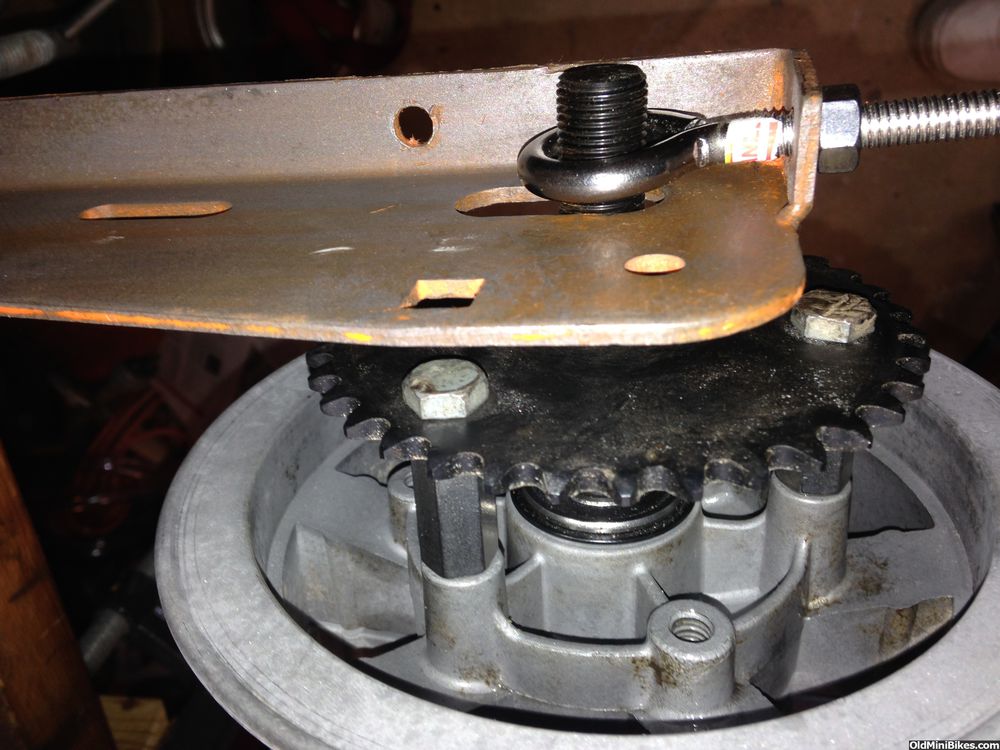
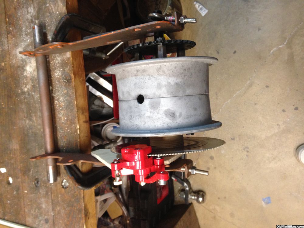
I'm going all out on this bike so it's getting disc brakes front and rear. Of course there's no disc hub that'll adapt to 1970s Bosch wheels, so they will have to be machined by a shop.

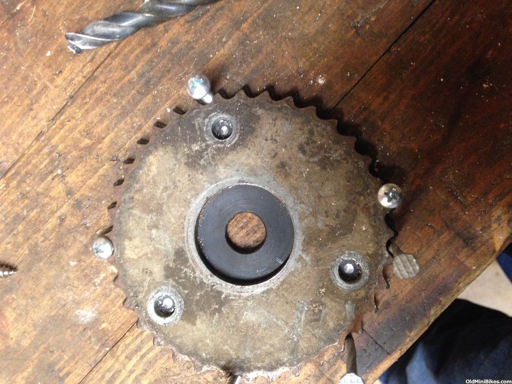
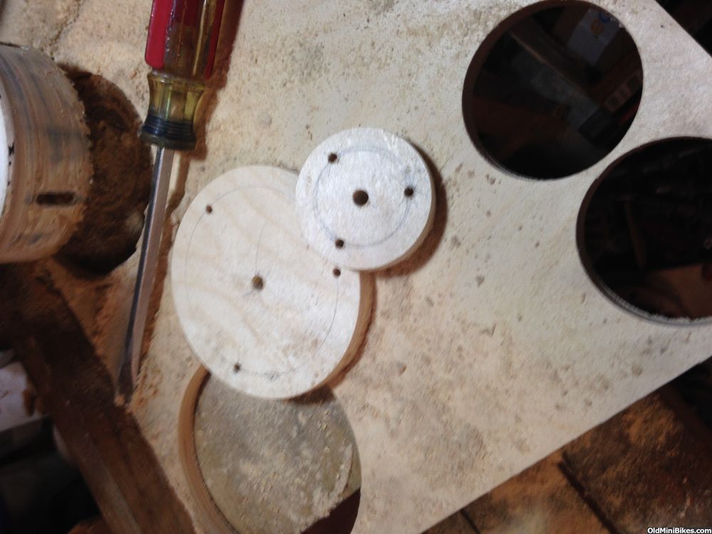
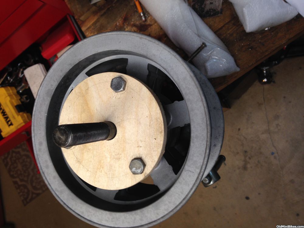
I needed to figure out the bolt circle so I could make the plate that'll mount to the wheel. I found 36 tooth blank sprockets at Gamut (a division of Graniger), and I had a pretty worn out original. To get the proper pattern so I could measure it, I put the new sprocket on the bench and used 3- #10 sheet metal screws to lock the OG sprocket to the new one. I had to use the bottom diameter of the sprocket (see below) to secure.


I used a 5/16" bit to locate the hole centers.


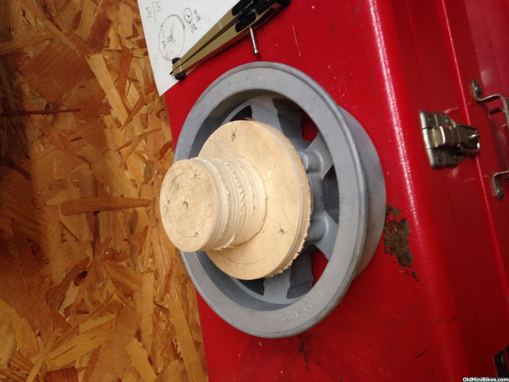
Here's a hint: Often you'll get an optical illusion that makes the mating pieces look like they are not lined up properly. I used the gridlines in my phone's camera to check my work as they help with any eyeballing necessary.

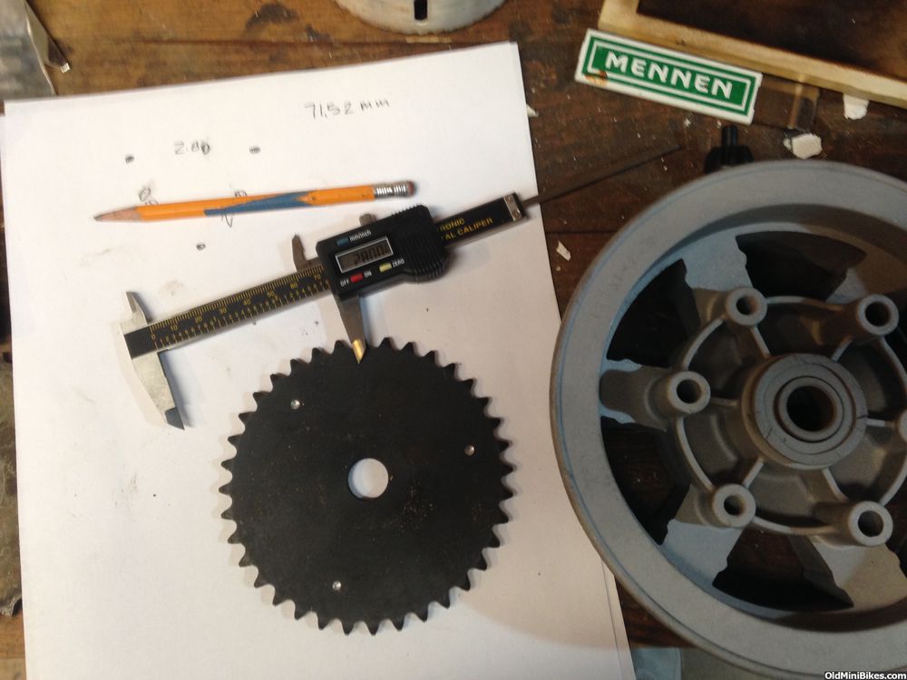
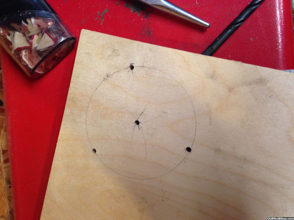
I drilled 3/16" holes in the sprocket and then used a punch to mark the bolt circle on card stock. I used my caliper to measure the distances between hole centerlines, checked against both the wheel and the original sprocket--2.80"


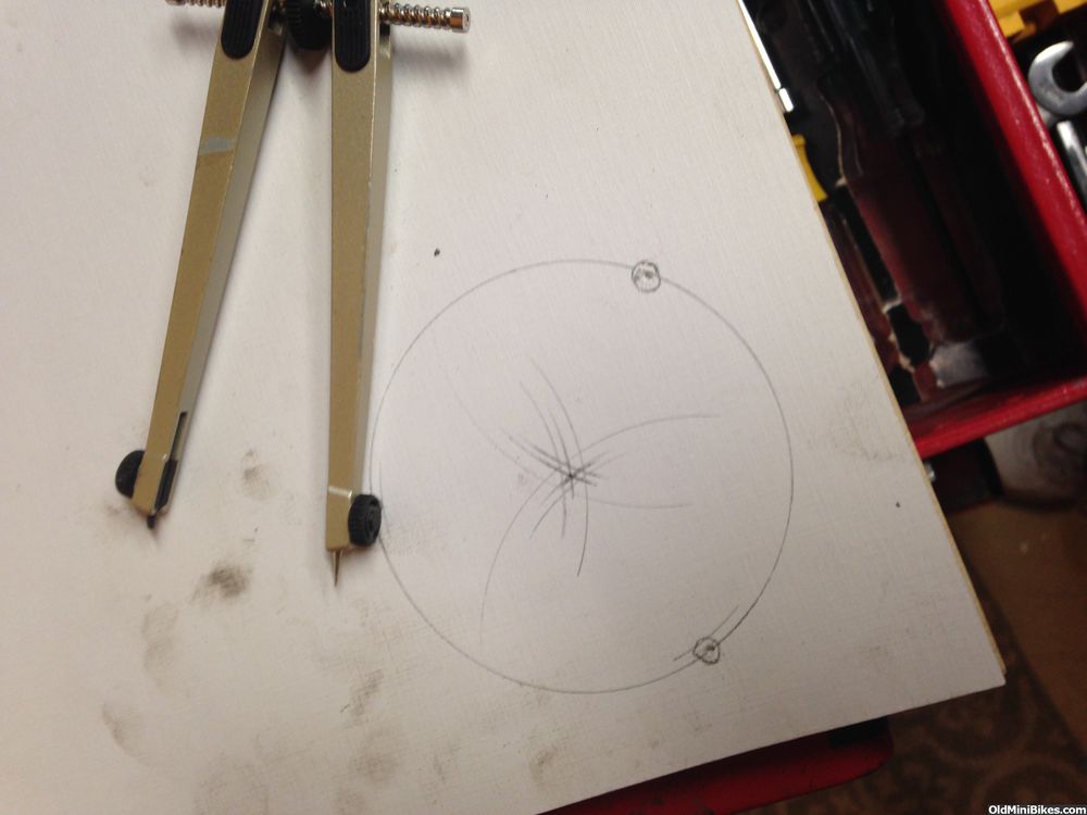
I used a compass to locate the center of the bolt circle--all trial and error until I found the sweet spot. This gave me a template to use when I do a CAD drawing of the part.

 
#15
Let's go modeling! #2

I used 3/8" hobby plywood for the mounting plate. I predrilled with a 3/16" bit after laying out the bolt circle using my template.


I used a 4" hole saw for the wheel plate and a 2 1/2" for spacers.


Here's how it looks stacked up:
 
#16
Let's go modeling! #3

Next up was attaching the sprocket to the wheel with 1" spacers (actually threaded rod couplers). I used stainless steel couplers not because I wanted to but because they are a smaller OD than plated spacers. The larger diameter couplers actually interfered with the base circle of the sprocket.

I'm a little anxious about using a 36t sprocket given the torque the engine will have. Maybe a 60t would have been the better choice: more teeth in contact with the chain. I'm using a OldMiniBikes double threaded axle.


On the opposite side, 5/8" center hole using a Speedbor bit and 3/8" holes for the bolts.


Here's a mock up with a 140mm diameter sprocket.


The 140 mm is too small to work with the swing arm. I had a 180 mm sitting around but its bolt circle is going to interfere with the wheel bolt circle (4 bolt v. 3 bolt). Back to the drawing board....:shrug:
 
Last edited:
#17
Let's go modeling! #4

First, I have no idea what happened to the uploads. The pictures rotated to the left 90 degrees so my apologies, in advance.

I decided to go with Motovox MB11 Rotors as they are 180mm. This will give me good clearance around the swing arm. Since i don't have them yet, I substituted a 7 1/4" (184mm) panel saw blade (Thanks, Papisty) with a 5/8" arbor hole. I needed to make a paper template of the "rotor" to begin to fuss with a caliper mounting plate. The paper template (not shown) is 3/8" larger in diameter. I started with a vertical alignment of the caliper thinking it would just clear the shock...not exactly.


The square hole in the swing arm is the carriage bolt hole for the lower shock. The adjusting knob for the caliper just interferes with the lower shock tube. I'll need to rotate the caliper back to the right about an inch.


Here's a look from the rear. Plenty of space side to side as opposed to the OG Gilson band brake design.


Here's a shot of how little clearance the OG band brake has side to side; very difficult to assemble.


Next is a new prototype for caliper the mount.
 
Last edited:
Top