Good evening,
SUMMARY:
Is a PZ19 (or any similar sized carb - PZ20, VM22, etc...) suitable for a B&S Quantum 190cc 124T flathead engine (These models no longer have a power rating but I assume it's a 4-5HP)?
UPDATE: I found some users talking about the Tecumseh HS50 engine (which has similar displacement and power) and they said that stock,
the PZ16 is actually a very good carb and both 19/22mm are suitable if some mods are done and need rejetting. Does anyone have any experience regarding this?
FULL STORY:
I'm learning a lot from reading all the posts here. However, I need some guidance, if possible.
I'm an engineering student and am currently working on a project where I have to modify two flathead engines to compare the performance between stock and opposed piston engine configuration.
Due to the unique configuration and flathead engines not being readily available, I ended up buying two B&S 124T engines.
I've been preparing all the parts for modifying but I lack the experience and would deeply appreciate all your experience regarding a few issues I have.
- Initially, I wanted to use the stock carburetors (reference 799866). However, these flo-jet carbs are very basic and don't allow any tuning. Also, the modifications necessary to be able to throttle and choke make it more complex since I wanta single throttle for both carbs. As such, II'm considering replacing the stock carb with a PZ19 or PZ20 which would make my life easier and allow for tuning the carbs. However, these seem to be for up to 125cc engines, not 190cc such as this engine.
The idea here is not to get the best performance but to compare the performance gains, therefore I do not need the best carb but it should be compatible and suitable to this engine.
I can either install a similarly sized carb (19mm) or adapt the intake to a 27-30mm carb. However, after reading some threads, it seems that for these lower power engines, the PZ19 or PZ20 should be enough since the performance is going to be kept close to stock.
By the way, no port modifications or compression ratio changes are going to be made since that's not the objective of the project.
Also, the ID of the port is 19mm, the original intake manifold pipe is 16mm ID and the carb is 19mm ID as well.
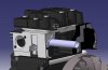
I disassembled the entire engine and will keep the stock exhaust, disable the governor and modify the intake so that the carburetor will end up above the flywheel and starter, through the shroud.
Also, the petrol to be used is 95 octane E5 (it's the standard rating in my country).
Also, I can always make an adapter for a larger carburator and reduce the ID to the 19mm at the engine intake but I feel that I won't have any gains by installing a larger carb. And I may end up reducing the throttle response.
Could you shed some light?
- Also, I've read some people talking about deleting the exhaust muffler. I can delete the muffler and use a 90º bend and straight pipe. It even would be useful in the long run once a turbocharger and electronic injection system are installed. But will it reduce performance, increase or not have any significant impact (due to the back pressure)?
- Any more advice, questions, suggestions?
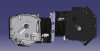
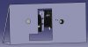
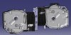
I can share some pictures of the project as it will go along if you are interered.
Thank you all for the help,
Best regards,
Alexandre
PS: The engine models are similar to the 124T engine.
The shaft output will be horizontal, the exhaust will probably be kept stock (one pointing to the bottom and the other to the top) and for the intake, I am going to make an adapter to remove the 90º bend and go straight to the back.
SUMMARY:
Is a PZ19 (or any similar sized carb - PZ20, VM22, etc...) suitable for a B&S Quantum 190cc 124T flathead engine (These models no longer have a power rating but I assume it's a 4-5HP)?
UPDATE: I found some users talking about the Tecumseh HS50 engine (which has similar displacement and power) and they said that stock,
the PZ16 is actually a very good carb and both 19/22mm are suitable if some mods are done and need rejetting. Does anyone have any experience regarding this?
FULL STORY:
I'm learning a lot from reading all the posts here. However, I need some guidance, if possible.
I'm an engineering student and am currently working on a project where I have to modify two flathead engines to compare the performance between stock and opposed piston engine configuration.
Due to the unique configuration and flathead engines not being readily available, I ended up buying two B&S 124T engines.
I've been preparing all the parts for modifying but I lack the experience and would deeply appreciate all your experience regarding a few issues I have.
- Initially, I wanted to use the stock carburetors (reference 799866). However, these flo-jet carbs are very basic and don't allow any tuning. Also, the modifications necessary to be able to throttle and choke make it more complex since I wanta single throttle for both carbs. As such, II'm considering replacing the stock carb with a PZ19 or PZ20 which would make my life easier and allow for tuning the carbs. However, these seem to be for up to 125cc engines, not 190cc such as this engine.
The idea here is not to get the best performance but to compare the performance gains, therefore I do not need the best carb but it should be compatible and suitable to this engine.
I can either install a similarly sized carb (19mm) or adapt the intake to a 27-30mm carb. However, after reading some threads, it seems that for these lower power engines, the PZ19 or PZ20 should be enough since the performance is going to be kept close to stock.
By the way, no port modifications or compression ratio changes are going to be made since that's not the objective of the project.
Also, the ID of the port is 19mm, the original intake manifold pipe is 16mm ID and the carb is 19mm ID as well.
I disassembled the entire engine and will keep the stock exhaust, disable the governor and modify the intake so that the carburetor will end up above the flywheel and starter, through the shroud.
Also, the petrol to be used is 95 octane E5 (it's the standard rating in my country).
Also, I can always make an adapter for a larger carburator and reduce the ID to the 19mm at the engine intake but I feel that I won't have any gains by installing a larger carb. And I may end up reducing the throttle response.
Could you shed some light?
- Also, I've read some people talking about deleting the exhaust muffler. I can delete the muffler and use a 90º bend and straight pipe. It even would be useful in the long run once a turbocharger and electronic injection system are installed. But will it reduce performance, increase or not have any significant impact (due to the back pressure)?
- Any more advice, questions, suggestions?
I can share some pictures of the project as it will go along if you are interered.
Thank you all for the help,
Best regards,
Alexandre
PS: The engine models are similar to the 124T engine.
The shaft output will be horizontal, the exhaust will probably be kept stock (one pointing to the bottom and the other to the top) and for the intake, I am going to make an adapter to remove the 90º bend and go straight to the back.
Attachments
-
 88.2 KB Views: 42
 -
 97.6 KB Views: 42
Last edited: