LED bulb conversion?
- Thread starter Detasman
- Start date

The above wiring diagram with the rectifier will work just fine. On mine I put a 35 to 50 volt electrolityc cap between 1000 to 2000 MFD. across the + - of the DC output but it is not necessary unless you see it pulsing. This pic shows a cap like I use. Electrolytic caps have polarity and if you hook them up backwards they will explode or vent.
Thanks Dave. You are absolutely right. I rechecked that circuit and i had it wrong. Here's a corrected diagram showing ground going to the light and the hot wire being run through the switch. Does this look better?
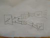
Ole4, is this what you said earlier? You install a diode in one of the AC supply wires, (yellow) with the anode- the straight line on the diode- on the side where the switch is. The yellow off of the switch is then DC positive. Ground comes from the lamp plug via the green wire.
If the LED flickers, install that capacitor with the positive side going to the yellow wire after the diode. The other side of the capacitor would be wired to ground.
?????
Thanks Dave. You are absolutely right. I rechecked that circuit and i had it wrong. Here's a corrected diagram showing ground going to the light and the hot wire being run through the switch. Does this look better?
Thanks Dave. The original (incorrect) diagram was also mine. The last diagram I posted shows the correct wiring. BTW, the diagram with the rectifier is also mine.
I was referring to the post before yours as being incorrect on the grounding/switch. Your first schematic would work.
Ole4, is this what you said earlier? You install a diode in one of the AC supply wires, (yellow) with the anode- the straight line on the diode- on the side where the switch is. The yellow off of the switch is then DC positive. Ground comes from the lamp plug via the green wire.
If the LED flickers, install that capacitor with the positive side going to the yellow wire after the diode. The other side of the capacitor would be wired to ground.
?????
Here is a schematic. Scroll down to half wave rectifier with smoothing capacitor, and disregard the "RL" resistor in the schematic.
https://www.electronics-tutorials.ws/diode/diode_5.html
https://www.electronics-tutorials.ws/diode/diode_5.html
I was referring to the post before yours as being incorrect on the grounding/switch. Your first schematic would work.
Ole4, is this what you said earlier? You install a diode in one of the AC supply wires, (yellow) with the anode- the straight line on the diode- on the side where the switch is. The yellow off of the switch is then DC positive. Ground comes from the lamp plug via the green wire.
If the LED flickers, install that capacitor with the positive side going to the yellow wire after the diode. The other side of the capacitor would be wired to ground.
?????
Ole4, is this what you said earlier? You install a diode in one of the AC supply wires, (yellow) with the anode- the straight line on the diode- on the side where the switch is. The yellow off of the switch is then DC positive. Ground comes from the lamp plug via the green wire.
If the LED flickers, install that capacitor with the positive side going to the yellow wire after the diode. The other side of the capacitor would be wired to ground.
?????