New member Fox Frankenstein

#1
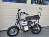
Hello all. I've been lurking for a bit and reading while working on my project along with my Dad. I'm not entirely sure what year/type it is but near as can tell it's a ~1970 Fox Street Scamp that we've been frankensteining together. My vision for it, terrible as that vision may be, is to have it look somewhat ratty when completely done, preferably without the mice that were living in the Tecumseh engine when it was started...

Anyway, we had his old HM80 from a long gone snowblower laying about, that fires and runs now after setting the points, putting in a new champion spark plug, and rigging a replacement $15 Chinese carb onto it. Put a 10 tooth 420 clutch down to a 15 tooth driven gear on the jackshaft. That runs to the original 35 chain 15 tooth and 70 tooth axle gears. On this setup it tops out at 35 mph (according to the speedometer app on my phone).

Life for it started out just seeing if the HM80 would fit. You can even see the original 2 speed jackshaft setup, now stored away as there is no room for it on this setup and replaced with its current setup.


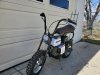
Upon completion of fabrication of the headlight and taillight using parts of a 1965 Buick Riviera (if there's any motorheads, it's okay they were clunker covers) the bike was named Rivenstein. The headlight has a 2500 lumen LED headlight and the taillight has an LED brake light in it that are awaiting wiring when I finish planning out the harness. It actually currently also has front and rear turn signals and a horn being added to the wiring and the left handlebar has the control hub for the signals, lights, and horn.


The fun really began when I first ran it. I quickly found out the mechanical brakes didn't feel like they were doing much to stop the bike. Really it seemed, even after a lot of tinkering with adjustments that simple entropy from friction was doing almost all the stopping and I decided to put a hydraulic brake on it. This led to some...interesting...fabrication as we are now at my parents second home and no longer have access to nice things like a welder, or a vice, grinder or what you expect in a shop. Left to my own devices, namely a saws all, hole drill set, and a drill and bits and a set of hand files I proceeded to build and mount a bracket to Rivenstein. The end product is functional, and as ratty as the rest of the bike. However, it now stops quite nicely with a grip that has a brake relay and a parking brake. In the future the front will also have a hydraulic brake mounted to it.


Future plans for the bike moving forward are to change out the original axle gear to a split gear adapter and drop down to a 53 tooth #35. The idea of going to the split gear on a universal adapter being to be able to play with different axle gears. Back at the shop several states away there is a TAV2 comet clutch that will fit the 1" crank shaft that will be installed. Sand blast everything and repaint it with the frame and forks going to a Ford engine blue. Matte black on the fenders, tank, and handle bars. Repaint the Tecumseh as close to its original color as possible. But that is months away. I'd like to get a video of it running and moving soon to upload as well.

Anyway, comments and tips/tricks are certainly welcome.
 
#2
Some more pictures I have showing the controls. It's sort of weird, to kill the engine the circuit is completed by turning it "on". The phone holder is to track my speed. You can see the mirror brackets for it as well.


The throttle was rigged up from the original. We got rid of the mechanism that sets it at different throttle levels to be able to hook it up to a throttle cable and a return spring was added as the spring in the carb wasn't nearly powerful enough.


Finally, a shot of it as it's currently sitting here in the front room. The jackshaft was reassembled today and everything on it has been tightened down and had Loctite added for extra measure to all the nuts and set screws. Currently waiting for the Loctite to set before taking it out again.


As an added note. The seat was sewn by my Dad back in the shop before coming down south. It turned out pretty nice, I think.
 
#6
I can see and understand the concerns with the brake caliper location. It will likely be revisited in the future when shop access returns. Put a bigger brake rotor on to make full use of the brake pads, for one. That will likely allow the caliper to move up more in line where the stock mechanical brake was between the swing arm and the shock. At its current location, the foot peg catches ground before the caliper does when turning but would be a bad location if off-roading on bumpy terrain.
 

River Rat Ron

Well-Known Member
#7
I can see and understand the concerns with the brake caliper location. It will likely be revisited in the future when shop access returns. Put a bigger brake rotor on to make full use of the brake pads, for one. That will likely allow the caliper to move up more in line where the stock mechanical brake was between the swing arm and the shock. At its current location, the foot peg catches ground before the caliper does when turning but would be a bad location if off-roading on bumpy terrain.
One thing to consider, bleeding the caliper is more challenging with the bleeder pointed down
 
Last edited:
#8
One thing to consider, bleeding the caliper is more challenging with the bleeder pointed down
You are correct, and even more reason to revisit this when shop/part availability change.

On another note, I've been spending my morning hours starting the layout of the wiring diagram. I'm using NanoCAD, a free AutoCAD clone to get this done.


nightgrider

Well-Known Member
#9
Some more pictures I have showing the controls. It's sort of weird, to kill the engine the circuit is completed by turning it "on". The phone holder is to track my speed. You can see the mirror brackets for it as well.


The throttle was rigged up from the original. We got rid of the mechanism that sets it at different throttle levels to be able to hook it up to a throttle cable and a return spring was added as the spring in the carb wasn't nearly powerful enough.


Finally, a shot of it as it's currently sitting here in the front room. The jackshaft was reassembled today and everything on it has been tightened down and had Loctite added for extra measure to all the nuts and set screws. Currently waiting for the Loctite to set before taking it out again.


As an added note. The seat was sewn by my Dad back in the shop before coming down south. It turned out pretty nice, I think.
Nothing wrong with a ratty Fox. Looks really good. This is my Fox campus. I'd love to have a Fox exhaust like yours.
 

Attachments

Last edited:
#10
Minor update. The wiring diagram, near as I can tell, is complete. It looks like the image capture is kind of garbage. I'll see if I can do better and edit this post later.


Edit: saved to PDF and converted to a JPG. Image now seems much more crisp. Added 5A fuse to diagram.
 
Last edited:
#13
Very cool, I like drawing out my diagrams. I’ll have to check out that program.
One thing, not seeing a fuse panel, or am I missing something?
One of the minor details I forgot was drawing in the fuse. I currently am planning on an in-line fuse on the main wire out. With a smaller 12v only system like this a full fuse panel shouldn't really be necessary from what I can tell in my research. The current system in total is a touch under 3A under full load. This means the intended 16ga wire with a 5A fuse should be plenty. 16ga wire can handle 13A and should handle the main line out without issue.

Haven't been around all day since I finished up the drawing because I started fabricating a bracket for the rear turn signals. I'll have to get a pic or 2 of the finished product. Already got some pictures I took during fabrication so I'll get them all uploaded and posted together after it's mounted to the rear fender. It's not the best I've done because the saws all got really jumpy cutting a 3/4" wide strip on that 1/8" metal.
 
#14
Well, the day got away from me. Regardless, the saga of the ugly bracket:

It started with the idea to put the bracket on the original holes in the rear fender. This required a bracket only 3/4" wide in order to fit and play nice with the new location for the fender bracket. Nice, now I don't have to fill those holes in and sand them smooth. The biggest problem though is not wide metal thing and saws all don't get along. You can see below my pattern cut from some aluminum sheeting and the chunk of steel I was cutting.


It went well enough considering the saws all was jumping around more than a toddler hopped up on energy drinks and I didn't have an actual press brake to make the bends and resorted to a channel lock and a hand held press brake. The end result in the following 2 pictures was...okay...but not very satisfying. When I have access to the shop again I'll have to take a second run at this bracket.


After all the madness of getting it made yesterday afternoon between other things I finally got it bolted on the fender today after a bit of hammering to curve it a bit to the fender. And yes, that fender is up very high because the bike sinks so very low. The springs in the shocks are 50+ years old and I am not a light person. You can see in the final pic how far the bike squats when I plant myself on it.


Overall, enjoyable, 6/10 final product, will fab again once back in the shop in a few months. Till the next misadventure, I ride off into the sunset.


Minimichael

Well-Known Member
#15
While I'm the first to say "if it ain't broke don't fix it," I did splurge and buy some new shocks for a vintage resto build and really love how comfortable (and adjustable!) they are.
 
#16
On my morning bicycle ride I ran across something rather interesting. Now, I've been wanting to put a back on my headlight that is preferably chromed. Ideally without paying to have it chromed. Just my luck, it seems the cover off a semi turbo popped off and was awaiting my passage. Patterning and fabrication to commence...sometime soon...

 
#17
Update on the project. These old rims have something funny going on. The tubes won't hold air anymore and based on the rattling when you turn them something came loose in the tire area and punctured the tubes. This actually turned out to be somewhat beneficial though. It means I get to pull apart the hubs and replace the bearings since the old bearings are original and while working are nearly dead.

This also means my plans for changing to a split sprocket has moved up significantly. Originally I had planned to move to a split sprocket when I changed to a torque converter several months down the road. So I now have a universal adapter on the way and a 53 tooth split sprocket. Since I can't find an adapter that will just bolt onto the Fox wheels It's gonna need some modification when it arrives. This shouldn't be an issue using the aluminum hub spacers as a pattern for the bolting pattern and hub hole sizing. Just a whole lot of tedious work to get the hub hole the right size.
 
#18
It's been a few days as I work on Rivenstein here and there as time permitted and waited on parts. The final part, being the split sprocket, finally came in Sunday afternoon. Anyway, by Friday I had all the stuff I'd ordered for my license plate bracket. I went on the KISS program for this and it's a couple frame clamps with a plate backer bolted to it. A couple LED plate lights and it was on the bike. No big deal there, was nice to have all the lights finally here and mounted to the bike. I mounted it vertically to keep the profile close to the bike.


Saturday the adapter came in, yay. As noted previously, I knew this thing wasn't going to just slide on the hub or even bolt into it. The first task was to make it fit the hub. So with a spiral sanding set for the drill and 5 hours of patience I eventually sanded enough aluminum off to be able to fit it to the hub as well as maintain it being centered within 0.1mm. Not bad considering I don't have a lathe handy...

After it fit the hub I was able to then put the spacer on top of it on the hub for drilling the holes. Doing this ensures that the holes are centered and I don't need to over-drill the size. I wish I had taken pictures of this process but at this point was in the mind set of just getting it done. After clamping the spacer to the adapter while they were on the wheel hub it was a process of drill hole, put bolt in to hold position. Rinse and repeat for all 4 holes.

Then it was just a matter of mounting the rear tire on. Figuring out the new length of the chain and removing extra length. Pulling the rear wheel back off to move in the swing arm since it wasn't playing nice and needed a few whacks with a rubber mallet to move. Putting the wheel and chain on to do final swing arm move to tighten the chain before torquing everything down again. Final product is below.


Taking it for a spin, it practically glides up to the 25mph speed limit and the engine is still just puttering along at that speed. Some math tells me that with my current setup the top end is somewhere around 53mph but I don't want to try to push that till I have safety equipment for myself. Till then I'll use it to putter around the village here at the 25mph speed limit and get started on all the wiring.

Speaking of wiring, I thought up something nifty. Sometime in the future I want to convert from a total-loss system to a regenerative system. This means adding an alternator, as that is the easiest method. Smaller Kubota tractors have a permanent magnet 14A alternator that you can buy aftermarket. Hook this into a rectifier to make DC output and bam, no more short night rides. That's a long way off though I think but I did update my wiring diagram to add provisions for its when that happens.


Edit: Added close up of axle gear.
 
Last edited:

Minimichael

Well-Known Member
#19
Great handiwork, and explanation. I too wish you'd taken pics of that hub work. That you got within 0.1mm shows you're a true craftsman. And the alternator part of your project will have my attention as well. Keep up the good engineering. You're inspiring some people on here...
 
#20
Entropy gets all things. The epic rattling of this bike gets all connections that are not tough enough. One of the brackets that was made for this was to adjust the angle of the carburetor and it snapped a weld recently. This means that I will now go back to this design and make some modifications to it to withstand the forces applied to it. As it seems that welds won't hold, the plan is to update this to use machinist bolts on the broken stud locations. Below is a picture of the fabrication done to rotate the carb as well as the handiwork of constant vibrational forces.


Updates to come, hopefully later today when modification has been completed. I plan to start the wiring harness this afternoon/evening.
 
Top