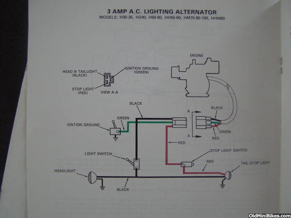
H50 lighting coil question .... why 2 positives?

One to the headlight one to the tail light. That's the way I remember it anyway .
There just isn't any other way to generate AC from a mechanical standpoint, give the parameters of the flywheel and ignition components. (A single coil would be enough to generate wattage for a battery charger, if only running LED bulbs, and NO electric engine starter)
Colors of the wires vary, but Tecumseh uses the center pin for the ignition shut off. Rupp used the red for tail/brake, and that's how I've always wired my various applications.
The two wires coming out of the lighting coil are just the wires coming from the coils some had 3 coils others had 2. The two wires will have the AC coming from the series wired coils. For use with a battery the two AC leads need to go to a rectifier (full wave for best results). Pit bikes have cheap ones for sale on ebay.
Male Plug Voltage Regulator Rectifier 4 Wire for Dirt Pit Bike ATV Quad Scooter | eBay
Male Plug Voltage Regulator Rectifier 4 Wire for Dirt Pit Bike ATV Quad Scooter | eBay
For use with a battery the two AC leads need to go to a rectifier (full wave for best results).
So if we attach both output wires to a single point in a bridge rectifier, we're going to severely limit the amount of voltage felt on the bridge, or worse case, (180 degrees out) double the voltage on both sides of the bridge.
I'm pretty certain that Ebay rectifier would work with one, but not both outputs. I do recall you attempting to parallel both sources and ran into this problem of wave cancellation as a voltage problem.
Still two rectifiers could provide ensuing pulsating DC to a VR and do a great job of charging a battery even while using lights.
Correct me if I'm wrong. It's been years. Paralleling three phase alternators results in a special kind of explosion.
There is an inherent problem using the same rectifier (even if it is bridge) with two alternators. We can assume the terminal voltage is the same, and we can assume the frequency is the same, however we will never achieve proper phasing between the two AC inputs.
So if we attach both output wires to a single point in a bridge rectifier, we're going to severely limit the amount of voltage felt on the bridge, or worse case, (180 degrees out) double the voltage on both sides of the bridge.
I'm pretty certain that Ebay rectifier would work with one, but not both outputs. I do recall you attempting to parallel both sources and ran into this problem of wave cancellation as a voltage problem.
Still two rectifiers could provide ensuing pulsating DC to a VR and do a great job of charging a battery even while using lights.
Correct me if I'm wrong. It's been years. Paralleling three phase alternators results in a special kind of explosion.
Expect a PM if I have issues sorting the VT out ... :bowdown:
dave I just checked my lighted hs50 and it has two coils 90 degrees apart and the coils are connected in between the coils and also go to ground then each far end goes to my connector. each coil measures the same around 1.1 ohms. I looked at my tec shop manual and they show about 5 different lighting coils one sounds like you are describing it shows one wire going to head and tail light and the other going to a stop lamp with no diodes used. Others with starters use the two AC lines going to full wave regulator regulator. I never had a issue using a tympainium type regulator rectifier on both my lighted tec's and clones. There are multiple poles on the internal magneto and mine are spaced 90 degrees apart and with coils wired in series they will both be in alignment with magnets at the same time so there is no out of phase issue with mine I am not sure about the OP's setup.
Damn Dave, I only understood about 1/2 of what your saying .. your one smart SOB!
Expect a PM if I have issues sorting the VT out ... :bowdown:
Expect a PM if I have issues sorting the VT out ... :bowdown:
The bulk of my techno-babble was directed at Ole's comment that one could wire both of these outputs to a single input on a full wave rectifier.
sounds like you are describing it shows one wire going to head and tail light and the other going to a stop lamp with no diodes used.
So my earlier comment was about applying both leads of this system to a common input on that e-bay fullwave rectifier.
The only way to isolate out of phase legs on either coil is to wire each output to a separate anode for half wave, with positive pulsating DC paralleled on a bus for the charging system.
Given that 1.1 ohm impedance, and -10VAC to +10VAC cycle, a current will exist on the coils before a load is ever applied, and power input will always be something less than 10VAC. That is why I questioned your comment, although it is valid with the other Tec alternators out there.
A thread on 3amp coil rectification.
I didn't mean to muck up the thread. MB165 did a lot of testing on this particular coil in an attempt to convert both coils into a single one so he could use it as a single power source. He could not, for the reasons stated. I wish I could find that thread.
Also, in a previous thread, I stated these were in series. I was wrong. They are two separate units, and become parallel when the outputs are wired together. (Just before they melt) On the other hand, I would be very interested to see someone risk that $100 replacement cost, and wire these two outputs together, and measure total output, as well as amperage. Not me. Someone else interested in debunking my version of Ohm's Law, LOL. :laugh:

yup im still messing with them. theres some info in the 2014 build off of the rupp. i took it to windber for the show this year it didnt leave the trailer, too muddy, again... i was dying to ride it after dark and light the place up...
you guys are correct, keep the coils separate, and use two regulators if DC is needed. tying them together wont work. maybe one coil for taillight and battery charge and the other coil for headlight?? one coil is more than adequate for a high power led headlight, it needs to be rectified and either a battery or big capacitor to smooth it out, lots of flicker at idle. i used a battery, if was going to build another one id go with a capacitor
if anyone fries a coil.... I can rewind them....
Dave you are correct with respect to the 3 amp red and black wires lighting coils, My ouput wires are both yellow. My tech manual just mentions the various 3 amp and a 5 amp version but no actual schematics showing how coils are wired. I have another magneto/lighting coil and tried to find it to look at it and see how the two coils are wired. If I can find it I'll post pics but I did not see if it is the same as the one I put in the motor I'm using for my rupp continental.
What I did was rectify only one output lead. On my Rupp Roadster II, I used that to charge a battery and run brake lights & a horn (fm a Honda). The AC line ran the headlight and rear running light.
My Rupp (just sold it at Windber '15) was street legal, so I wanted brake lights if the engine stalled.
My Rupp (just sold it at Windber '15) was street legal, so I wanted brake lights if the engine stalled.