nos tecumseh charging coil, factory high ouput option???

MB165

Active Member
#1
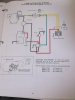
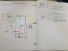
heres a interesting tecumseh lighting coil assembly. three coils.....tied together
with a connector that attaches it to a full wave rectifier regulator. when i saw the photo online
i didnt realize the lower right coil was tied into the setup.
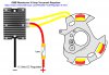
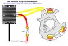
aside from the top coil which is 180 degrees from the lower left coil,
them being tied together is what we have all been after....getting those two hooked together for additional output. im gonna try and figure out what the secret is, feel free to jump in and help... if anyone has one or knows anything about it please chime in.
I looked in my tecumseh charging systems book best i can figure, it is a 7 or 10 amp setup (vs 3amp on our rupps). either way this is one heck of a powerful setup for a 3.5 or 4hp engine.

 
#2
Looks like it's set up to work with a rectifier box. Generally Tec uses red wires in their DC portions, and yellow for AC, green for shut off. I saw several versions in the book, but no definitive answers. Looks like anything from 5 amp to 7 amp in the book.

Getting the flywheel is the key, as well as taper for application, et.al. HSK?
 

MB165

Active Member
#3
i noticed the coils are in series. so is it that simple on the rupp setups to just series them instead of parellel?

It looks like if i test running voltage i can figure out which one it is.
7a is 14v at 3600 and the 10a is 20v at 3600
DSCF4396.JPG DSCF4399.JPG
 
Last edited:
#5
i noticed the coils are in series. so is it that simple on the rupp setups to just series them instead of parellel?
No, because as the magnets pass over the stator, their polarity changes, thus the voltage polarity changes on each individual coil. So combined voltages will be a negative plus a positive, and "less" than peak voltage. You just cant parallel them.

Another side effect is that the "less" positive voltage will be seen as a negative by the "more" positive coil, creating a current within the coils. That could fry them.
 
#8
its made in austria, 15 degree wedge....based on where i obtained it, its for gunsmithing, i dont know exactly what though
Ahhh now that I see it on my laptop screen I can see the wedge shape...called a "knife" file which are pretty common but I have never seen a file with an offset tang like that. Very interesting.

Ok sorry for interrupting, back to the electricity lesson...:biggrin:
 
#9
Cool file, even Pearson Higher Ed doesn't cover that offset tang. Gotta be for knuckle clearance...

That lower right coil is offset to generate in phase with the opposed coils. Since the extra coil is in phase with the opposed coils, but at half the Voltage, it could be wired to boost the Amps of the opposed pair.

Can't make out how the 3 coils are connected. Will draw a couple of diagrams if you want to Ohm it out or sketch how the wires connect.

Jon
 
Last edited:

MB165

Active Member
#13
no diodes, its screwy setup. the 3 term. connector is setup so the ac is on the outside, regulator dc output is the center terminal. that could go out to the piece of equipment. but they doubled it back around to the small connector so theres engine stop and charge output on the small connector.
 
#14
Hi Pete,

You SURE there's no diode? looking at the lower left coil which has a yellow wire going to the upper right coil, it looks to me they might have snuck one in there. That boot on the lower left coil looks really big. I am not doubting you, I am just wondering?

Doc
 
#17
Looks like a 3 Amp unit BikeBudy, and it has the correct pinout. Seen so many parts burn out I always go for super duty, plus its easier to duck if somebody roasts a heavier duty part.

If the lighting load is low enough Amps, that little unit might be OK. It would certainly hide better. I doubt it would endure the full output of these 3 coils.

updated: searching OldMiniBikes Warehouse again, found a 15 Amp regulator that is smaller and about half the cost of the 10 Amp device:

Jon

The search function on OldMiniBikes Warehouse is always my first reach, so I list parts from there first especially since I learn a lot at no cost to be here. OldMiniBikes Warehouse has real specifications on their parts, such as 10 Amps on the first regulator I posted. Many others claimed the same parts is good for 15 Amps.
 
Last edited:

MB165

Active Member
#18
ok, looking at the way tecumseh has assembled these coils. can we rewire the coils on the rupp stators (one coil at 5 and 7 like this one) with the outside of one coil feeding the inner of the next and get the higher output ive been trying to get?
 
Last edited:
#20
ok, so with the way tecumseh has assembled these coils. can we rewire the coils on the rupp stators with the outside of one coil feeding the inner of the next and get the higher output ive been trying to get?
Theoretically this would work. The aim is to wire the second coil exactly opposite of the first one. Since magnets are N-S, then N-S, it makes sense that you're building a positive voltage on coil A, while building a negative voltage on coil B.

Theoretically. You're still going to be at that 10VAC area with higher current. Or you'll melt coil A because at some point coil B see's so much negative that it views it as a dead short, and current flows. Interesting test though!

From the book:

When a conductor (alternating coils) cuts the magnetic field generated by the magnets in the flywheel, a current will be induced in the alternator coil. The permanent magnets in the flywheel have a magnetic field in which the lines of magnetic force run from the North Pole to the South Pole. As the flywheel rotates and the position of the magnets change, the direction of the magnetic field changes or alternates. The alternating coils are wound in different directions to allow current to flow as an A.C. waveform.
 
Top