I have a thread started in the mini bike forum titled “ 71 Muskin Cat 2501 Project”.
I am posting this thread here since it is Tecumseh engine specifically.
My H25 on the Muskin Cat is original to the bike. Here are some pics:
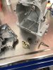
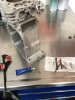
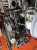
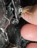
The first and second pics shows the governor arm-and how it is connected to the governor shaft coming out of the engine via the special triangular bracket. I had to replace the spring that goes from the governor arm to the throttle cable linkage, as it was all stretched out of shape. The carb is not the original one but it is a tecumseh replacement one. I had to straighten the rod from the governor arm to the carb as well.
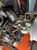
The third pic shows the throttle cable bracket setup which i believe to be original.
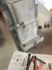
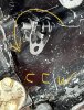
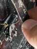
The 4th pic shows the governor shaft bracket ( without the Governor arm). It is rotated in the full clockwise direction.
The 5th pic shows the same governor shaft rotated to the full counter clockwise direction.
With out the governor arm attached the governor shaft does not bind and can travel fully cw and ccw.
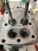
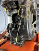
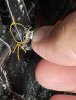
The 6th pic show me holding the governor arm in position while the shaft is at the CW position.
The 7th pic shows the governor arm hits the engine and prevents the governor shaft from achieving the full CCW position.
The 8th pic shows the Governor shaft bracket again. I assume this interference is not correct, and i am thinking the governor shaft bracket could be loosened up and slid forward and then re secured to the shaft, providing the necessary cleance so the governor arm can achieve the full CCW rotation.
Am i on the right track here with my investigation and theory?
Also there appears to be no rotational adjustment on the governor shaft and the triangular bracket. Is this correct? It seems to me it is “clocked “ in position to the shaft, but is can be moved in and out on the shaft a small amount.
Thanks in advance for comments or thoughts... Steve
I am posting this thread here since it is Tecumseh engine specifically.
My H25 on the Muskin Cat is original to the bike. Here are some pics:
The first and second pics shows the governor arm-and how it is connected to the governor shaft coming out of the engine via the special triangular bracket. I had to replace the spring that goes from the governor arm to the throttle cable linkage, as it was all stretched out of shape. The carb is not the original one but it is a tecumseh replacement one. I had to straighten the rod from the governor arm to the carb as well.
The third pic shows the throttle cable bracket setup which i believe to be original.
The 4th pic shows the governor shaft bracket ( without the Governor arm). It is rotated in the full clockwise direction.
The 5th pic shows the same governor shaft rotated to the full counter clockwise direction.
With out the governor arm attached the governor shaft does not bind and can travel fully cw and ccw.
The 6th pic show me holding the governor arm in position while the shaft is at the CW position.
The 7th pic shows the governor arm hits the engine and prevents the governor shaft from achieving the full CCW position.
The 8th pic shows the Governor shaft bracket again. I assume this interference is not correct, and i am thinking the governor shaft bracket could be loosened up and slid forward and then re secured to the shaft, providing the necessary cleance so the governor arm can achieve the full CCW rotation.
Am i on the right track here with my investigation and theory?
Also there appears to be no rotational adjustment on the governor shaft and the triangular bracket. Is this correct? It seems to me it is “clocked “ in position to the shaft, but is can be moved in and out on the shaft a small amount.
Thanks in advance for comments or thoughts... Steve
Attachments
-
 1.8 MB Views: 18
 -
 1.6 MB Views: 17
 -
 922.2 KB Views: 15
 -
 549.3 KB Views: 15
 -
 848.6 KB Views: 17
 -
 580.2 KB Views: 17
 -
 527.6 KB Views: 17
 -
 441.3 KB Views: 18
 ) you want to adjust it out CCW just so its out of range/barely making contact internally with the Flyweight/gear that inside when at WOT. That can only be achieved Running/testing (don't hold it WOT while running to adjust though! You can make those adjustments at idle though on the stand, at least I can). You want the parts to still be as close together inside as possible because if something was to go south inside the engine with the Gear assembly, your pivot/arm will still be there to prevent it from coming off the shaft inside...and it keep your pivot shaft safely away from the moving internal parts while still keeping the pivot point of the arm in a range where it will work the carb and throttle correctly.