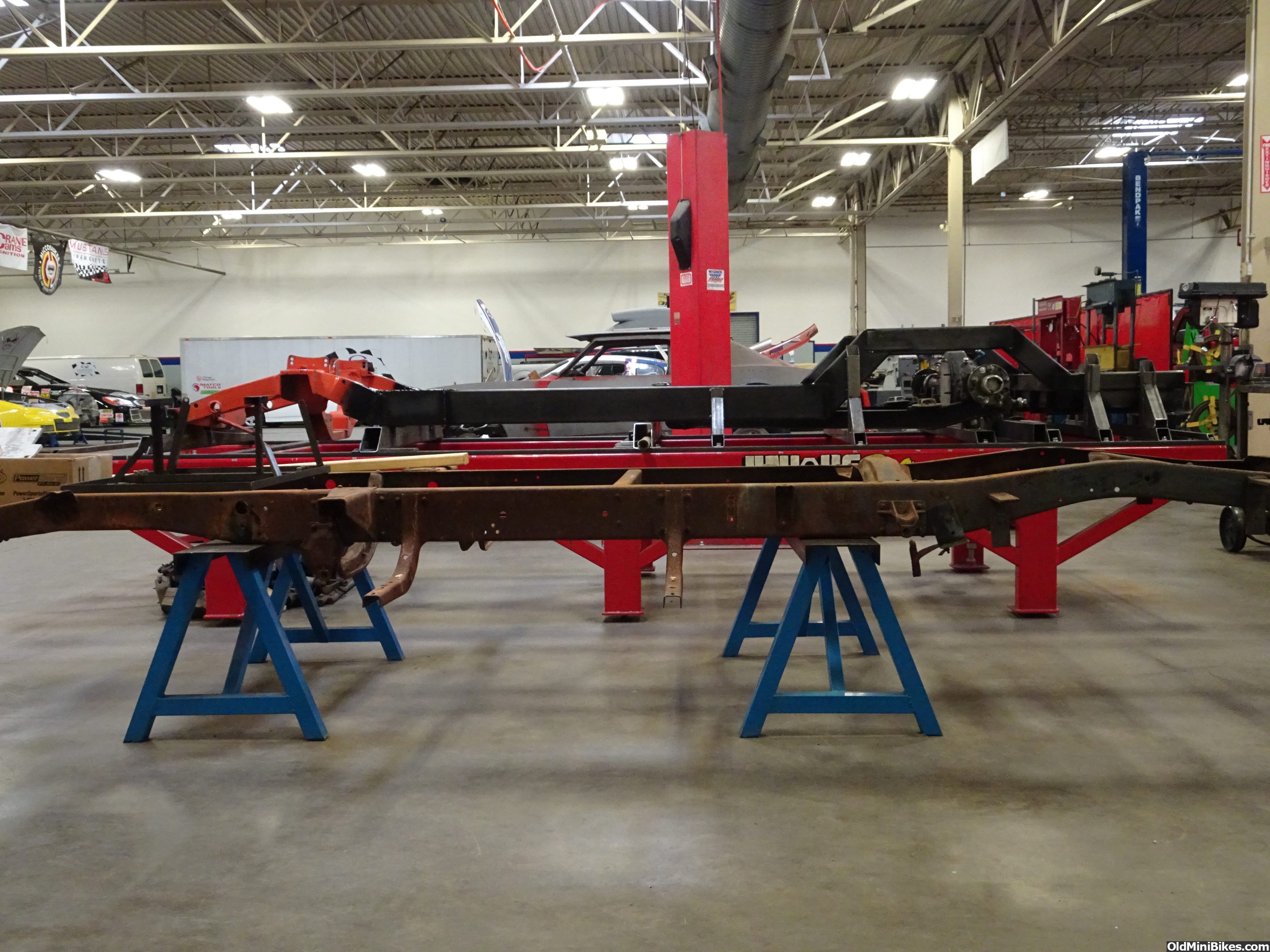
Wanted to post this for others to see the jig fixtures and how things are setup to build a full frame. Hopefully this will give visual help to someone trying to fixture and square things on something they are building.
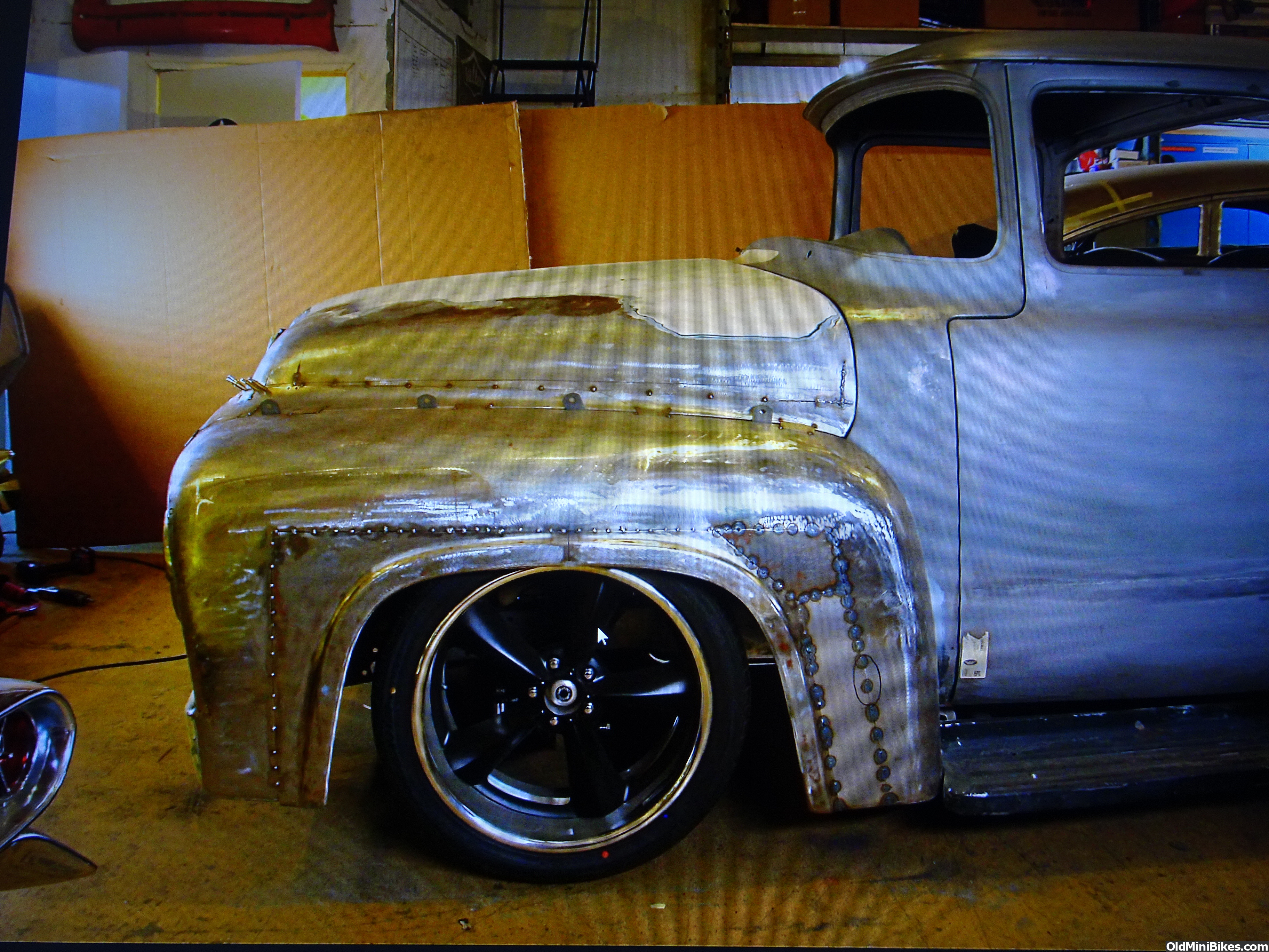
This is a frame that is going under my personal 1956 F-100.
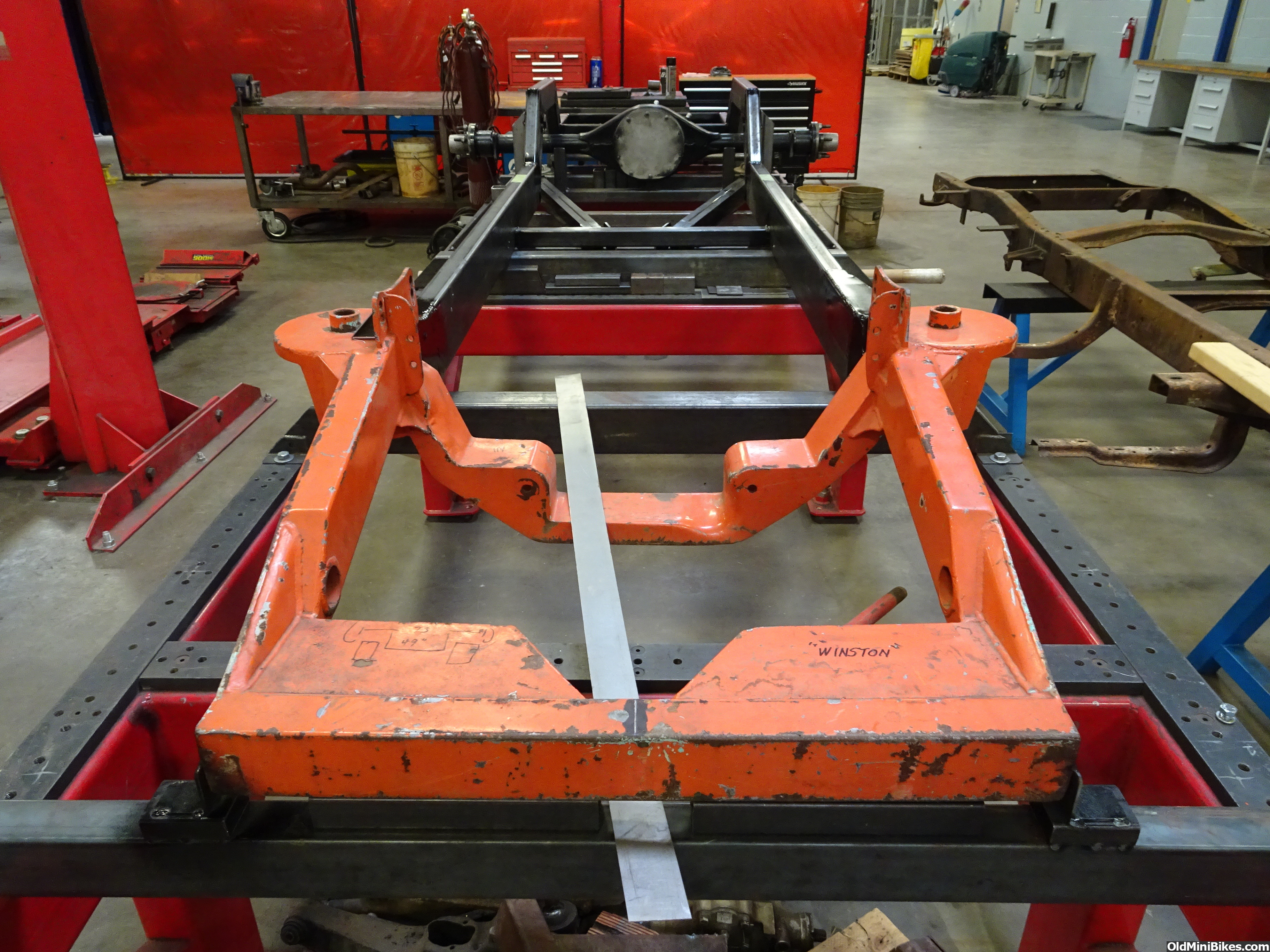
Just a little history on the front snout. I am using a fabricated front snout that I picked up back in the late 90's. It is a Bill Funderburk design fabricated snout. Funderburk worked at H&M from the middle 60's into the 70's then went on to build chassis for his self. These are based on a 1965 Galaxie "rear steer" frame. They were the dominant chassis design until someone (Bobby Allison gets the credit in most circles) came up with the GM "front steer" chassis. The rear steers down fall was that it picked up a push as the race progressed. You had to set them up with a lot of static toe in so that they wouldn't toe out later in the race. When the front steer cars didn't develop a push later in the race they were the cure to that ill handling problem.
I am building this to a Road Race chassis spec so that it will be a good street setup. The road race setups were equal right and left. The left turn chassis is skewed to turn left the best. I had to search for about 3 months to find a 9'' rear end housing that didn't have any camber in the tubes. Steve, the school instructor, had almost all of the front end components. Big brakes with 6 piston calipers, A-arms and steering that included a 16 to 1 Sweet Mfg power steering steering box. Would have liked for it to have been a 14 to 1 but the price was right.
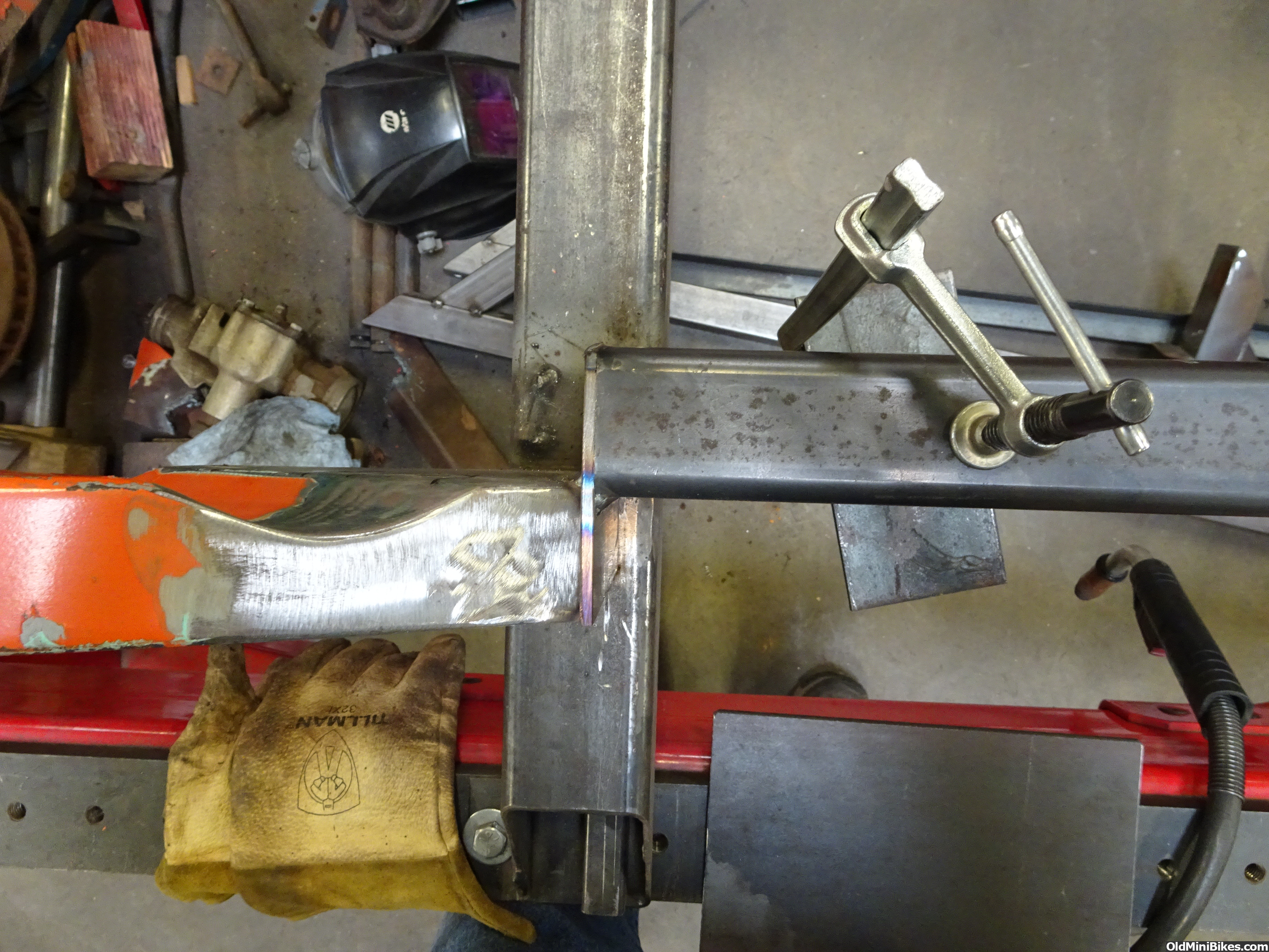
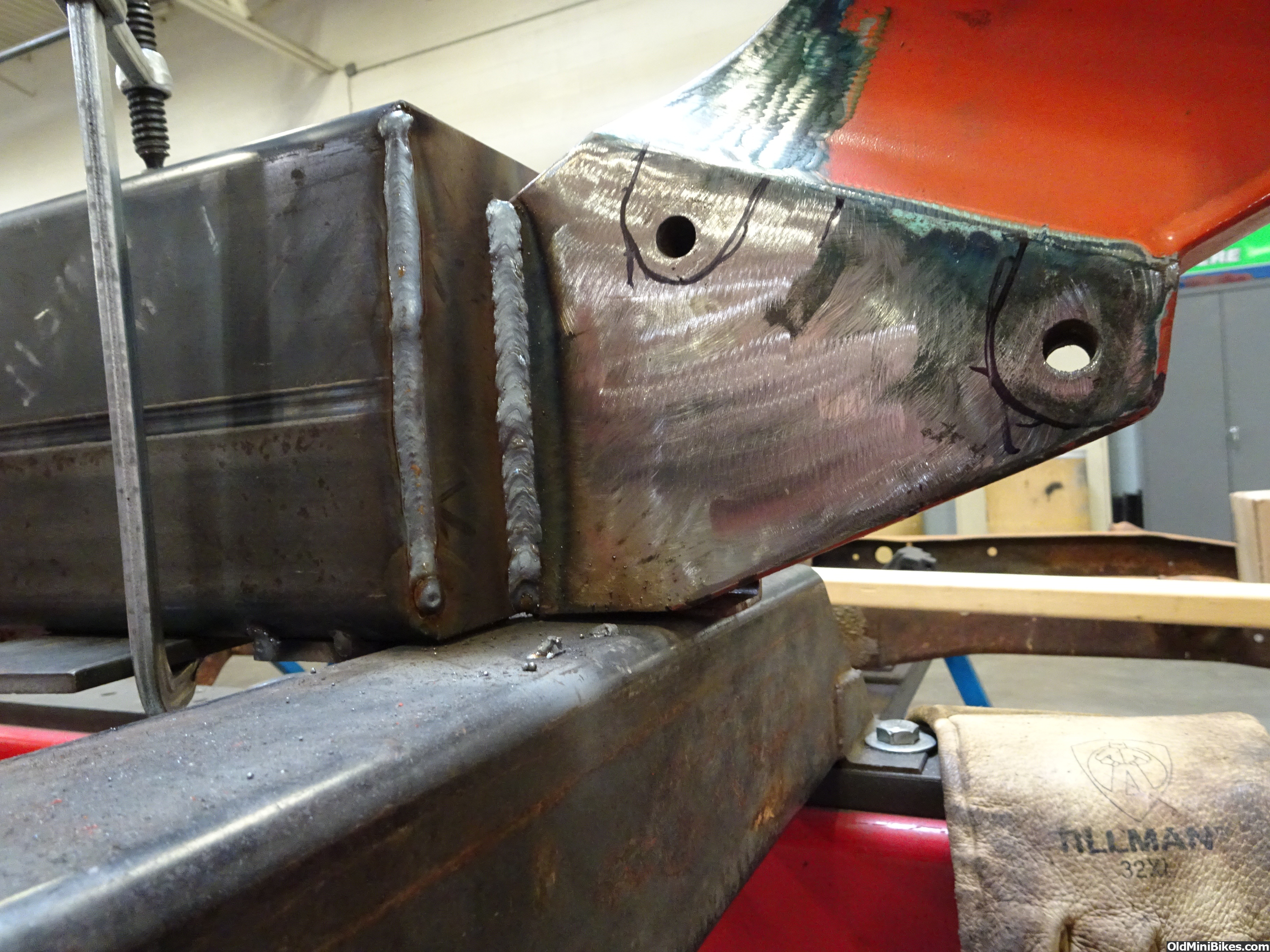
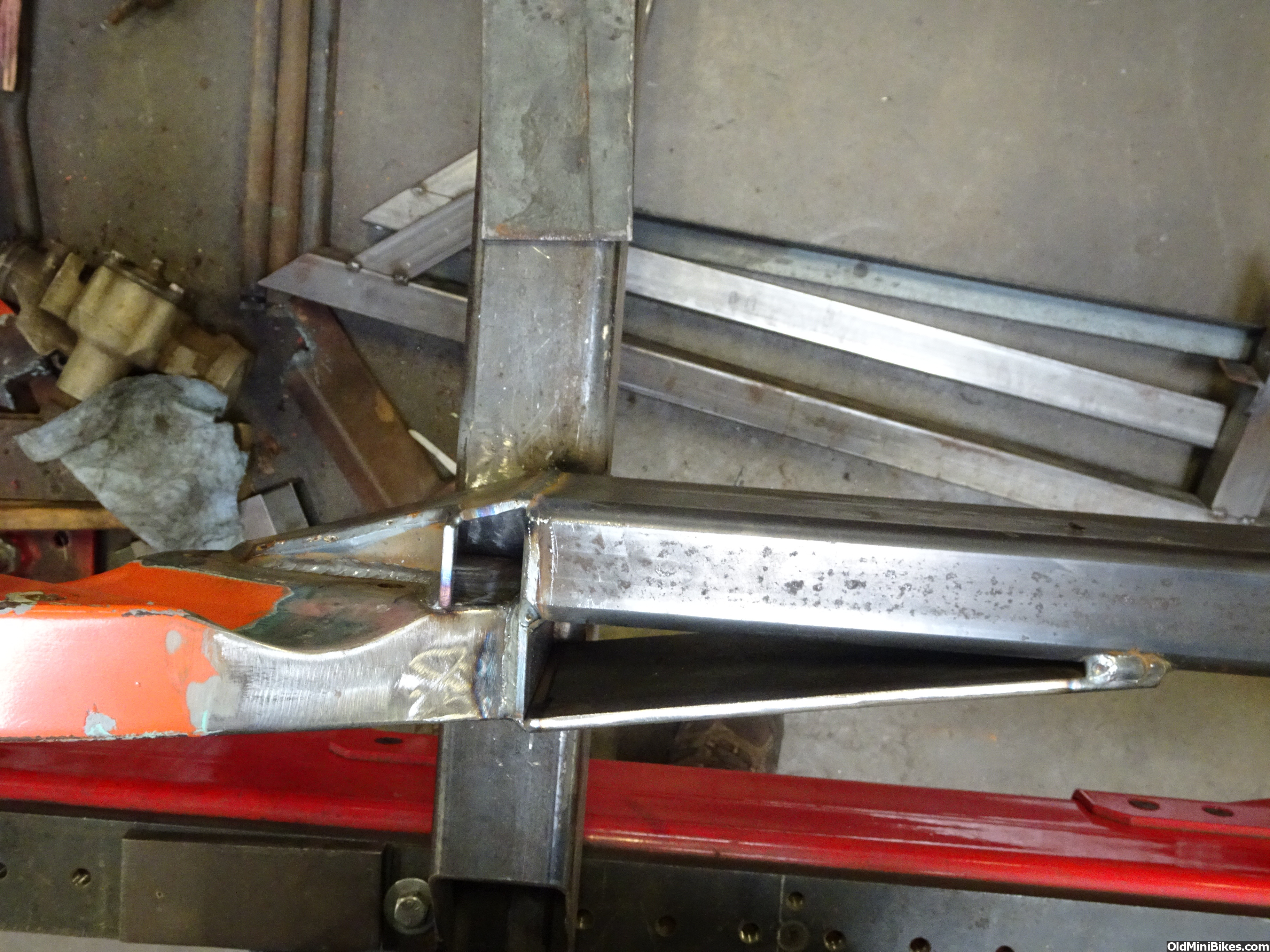
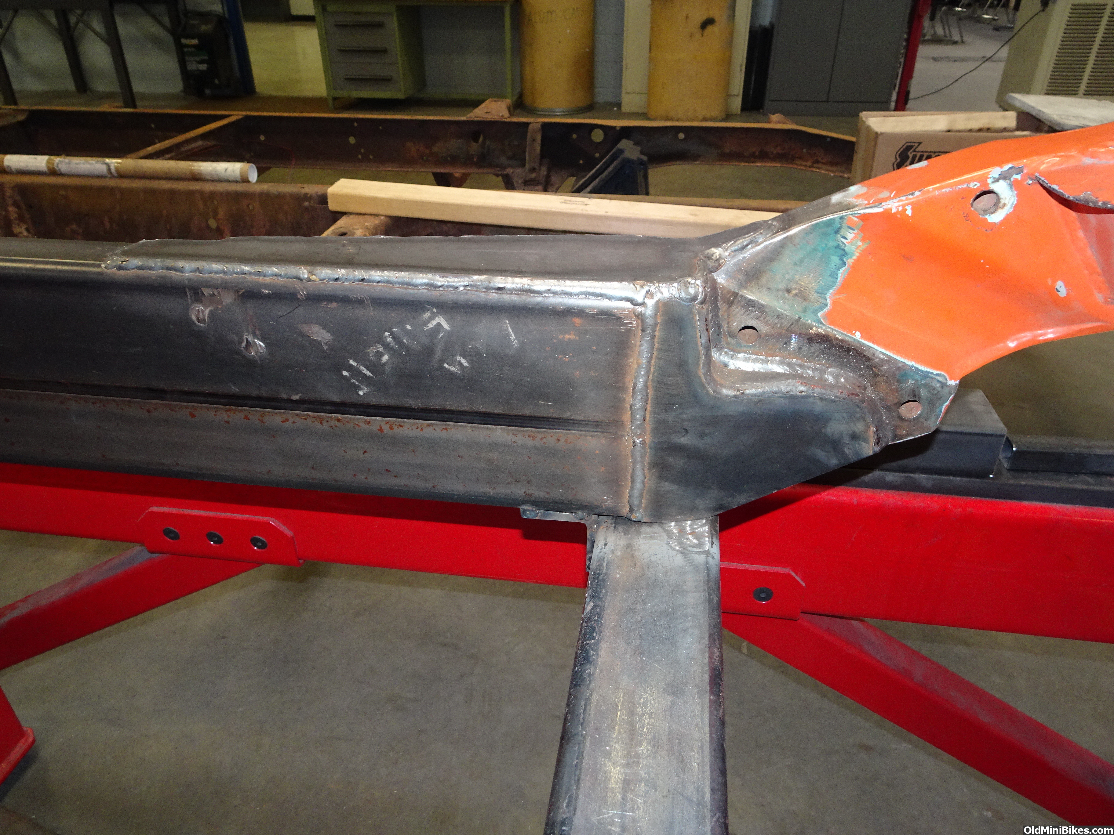
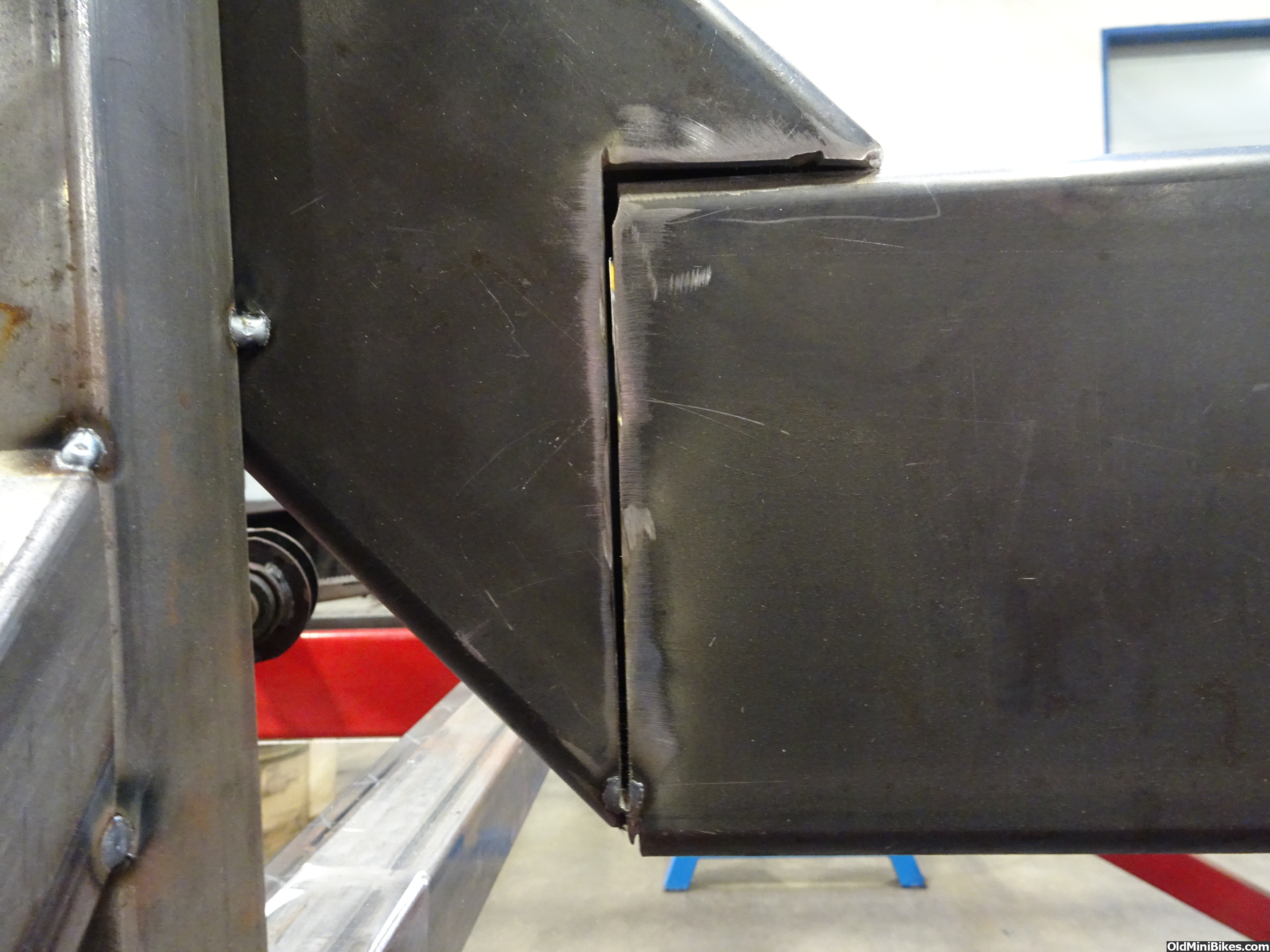
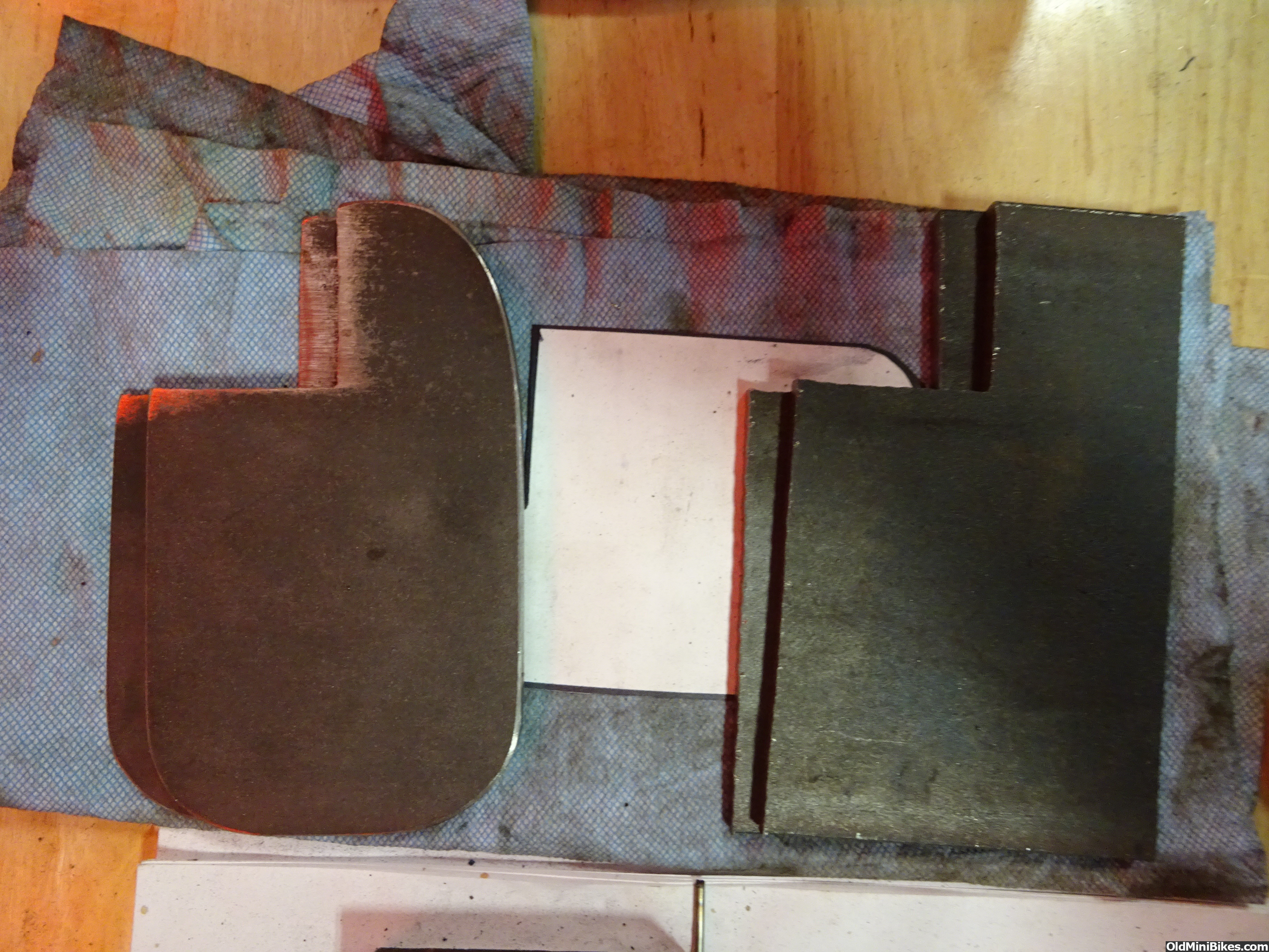
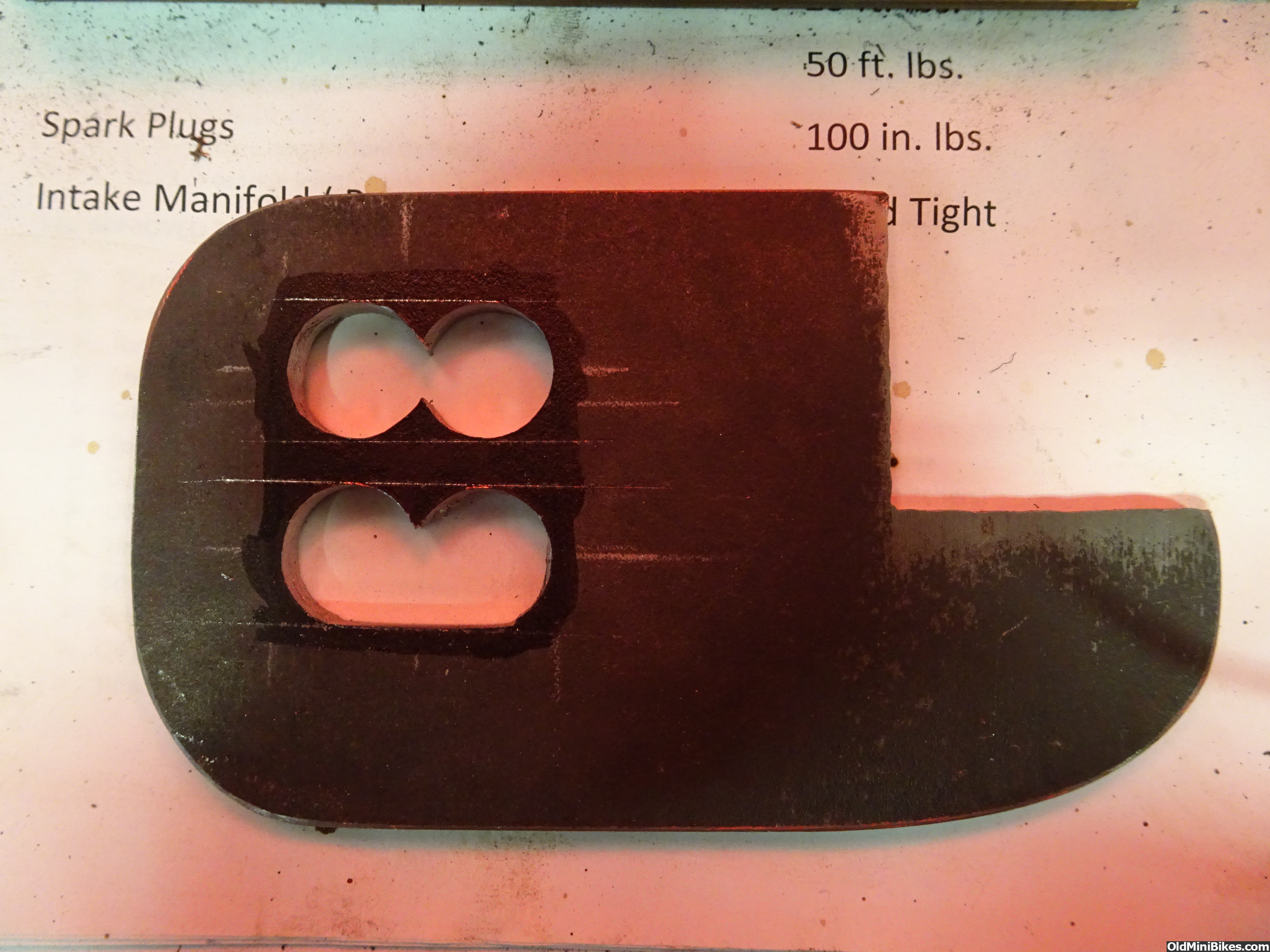
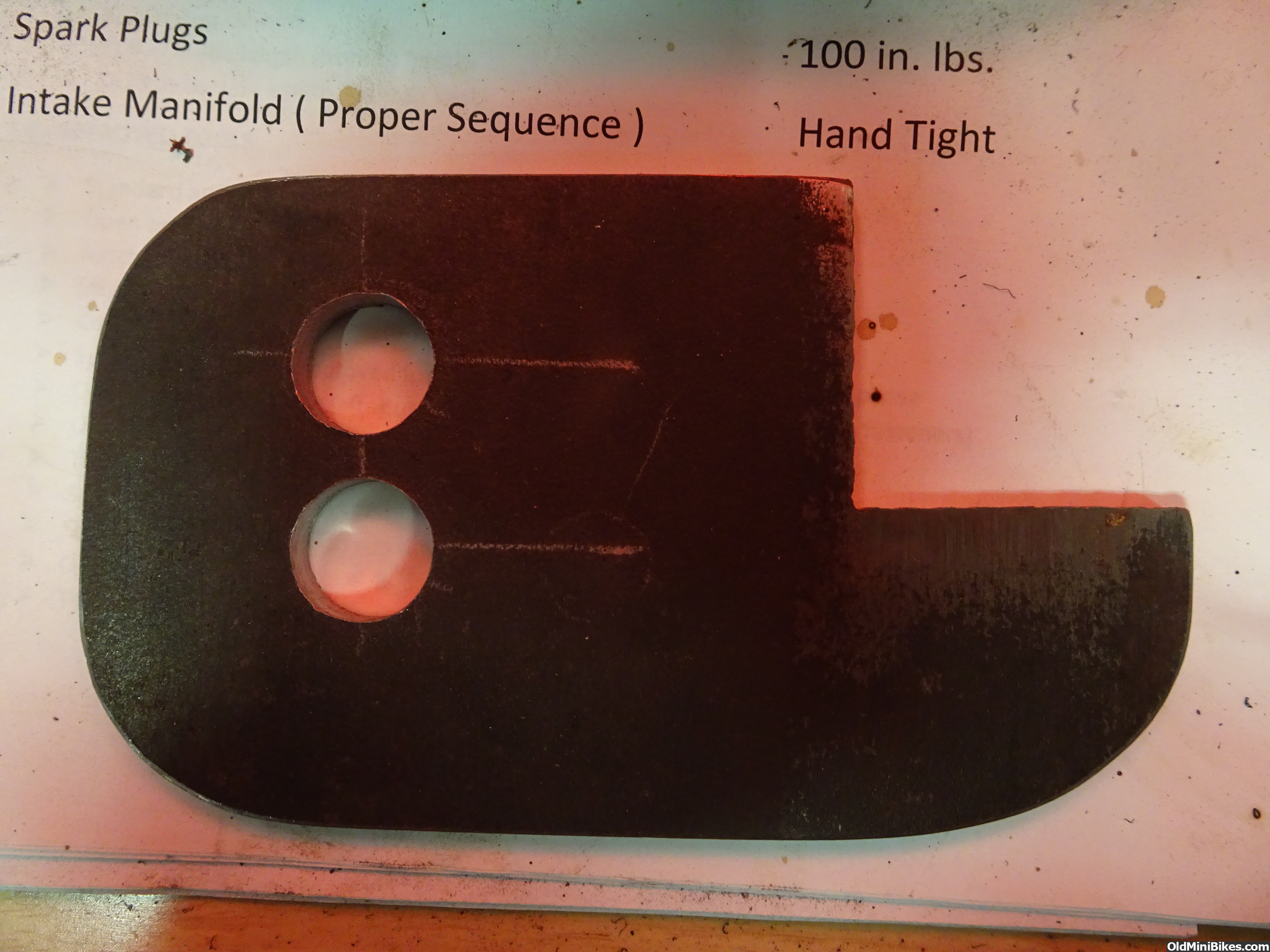
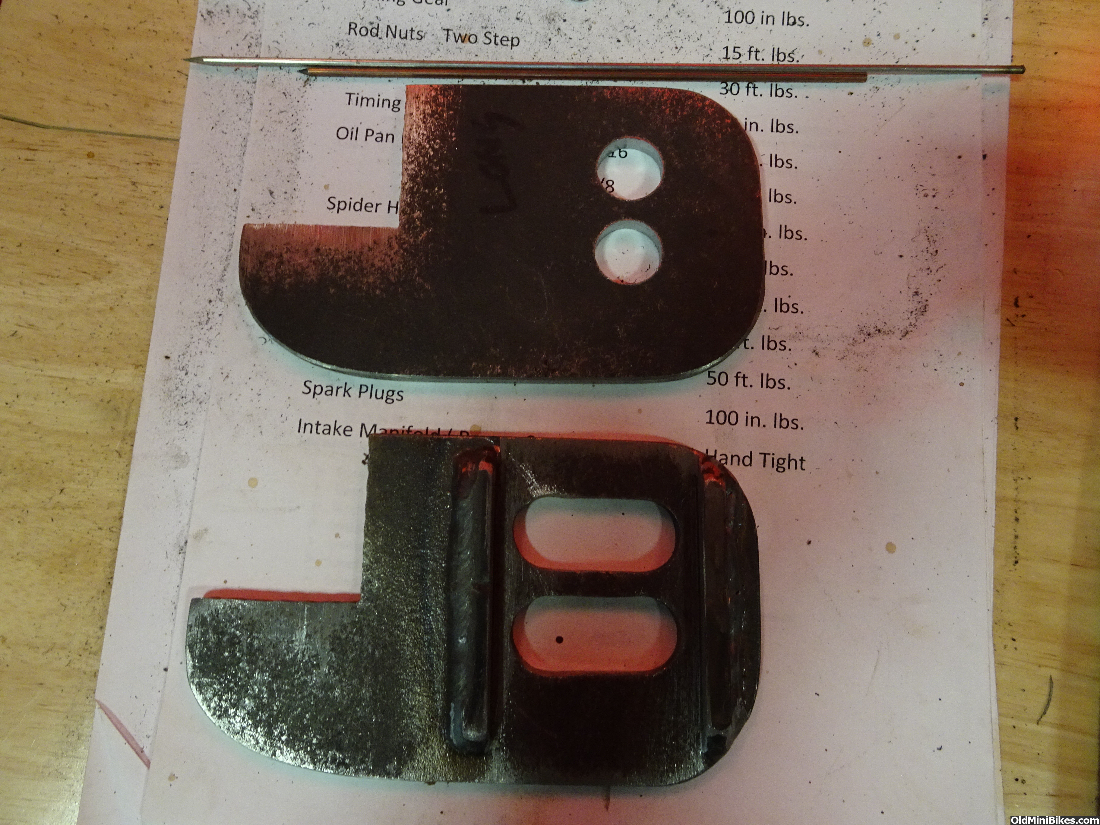
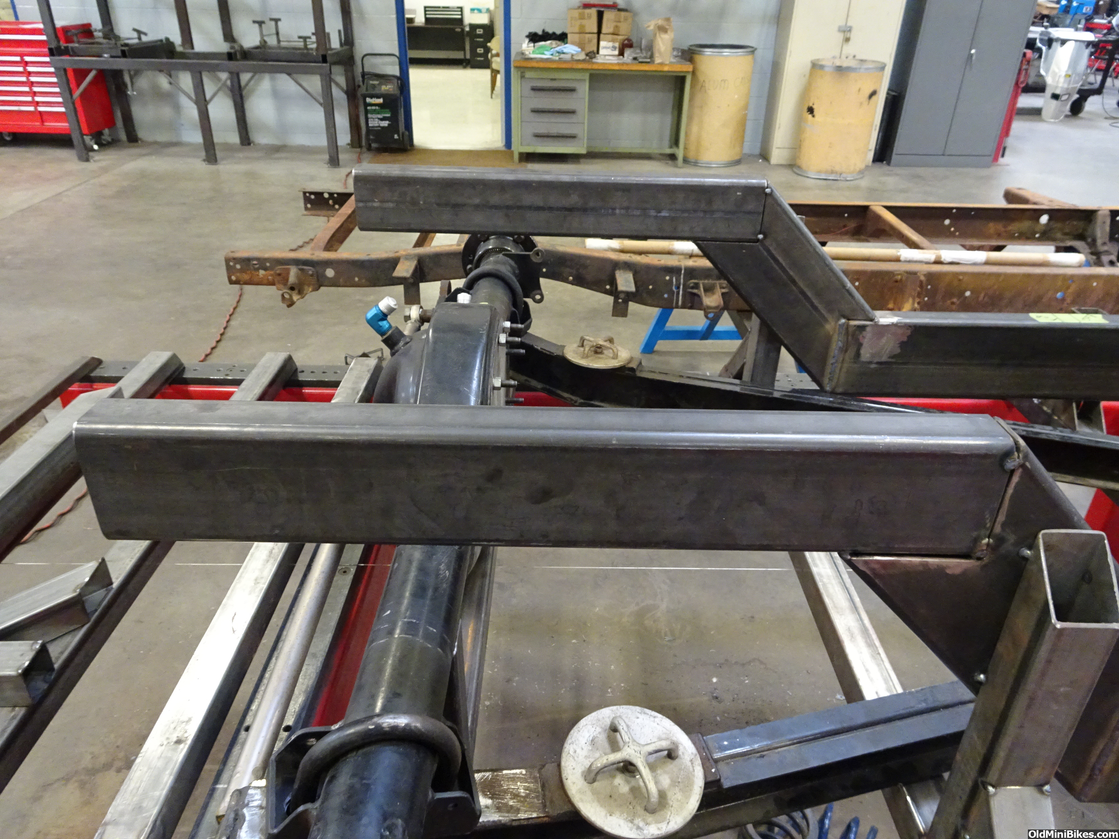
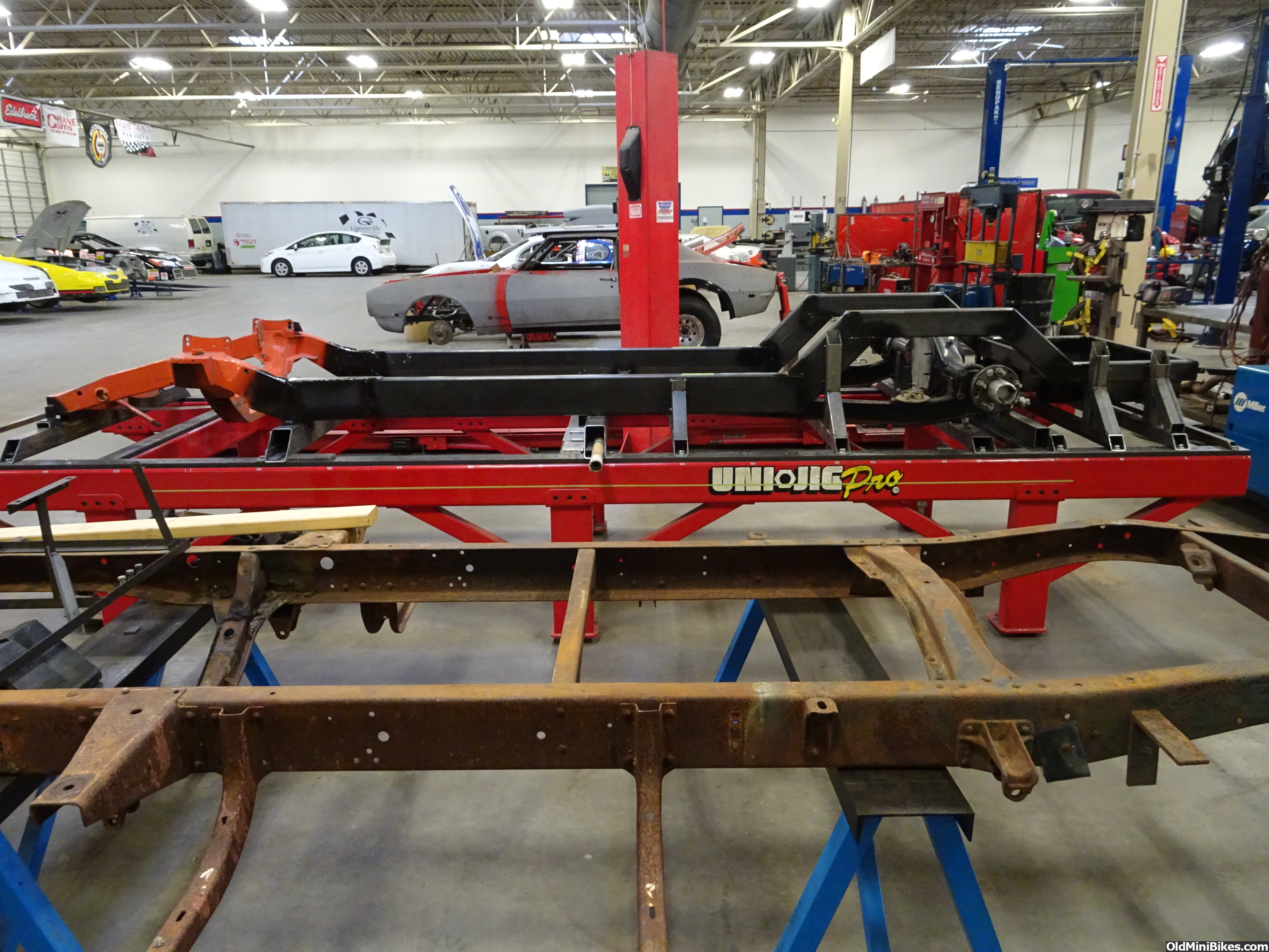
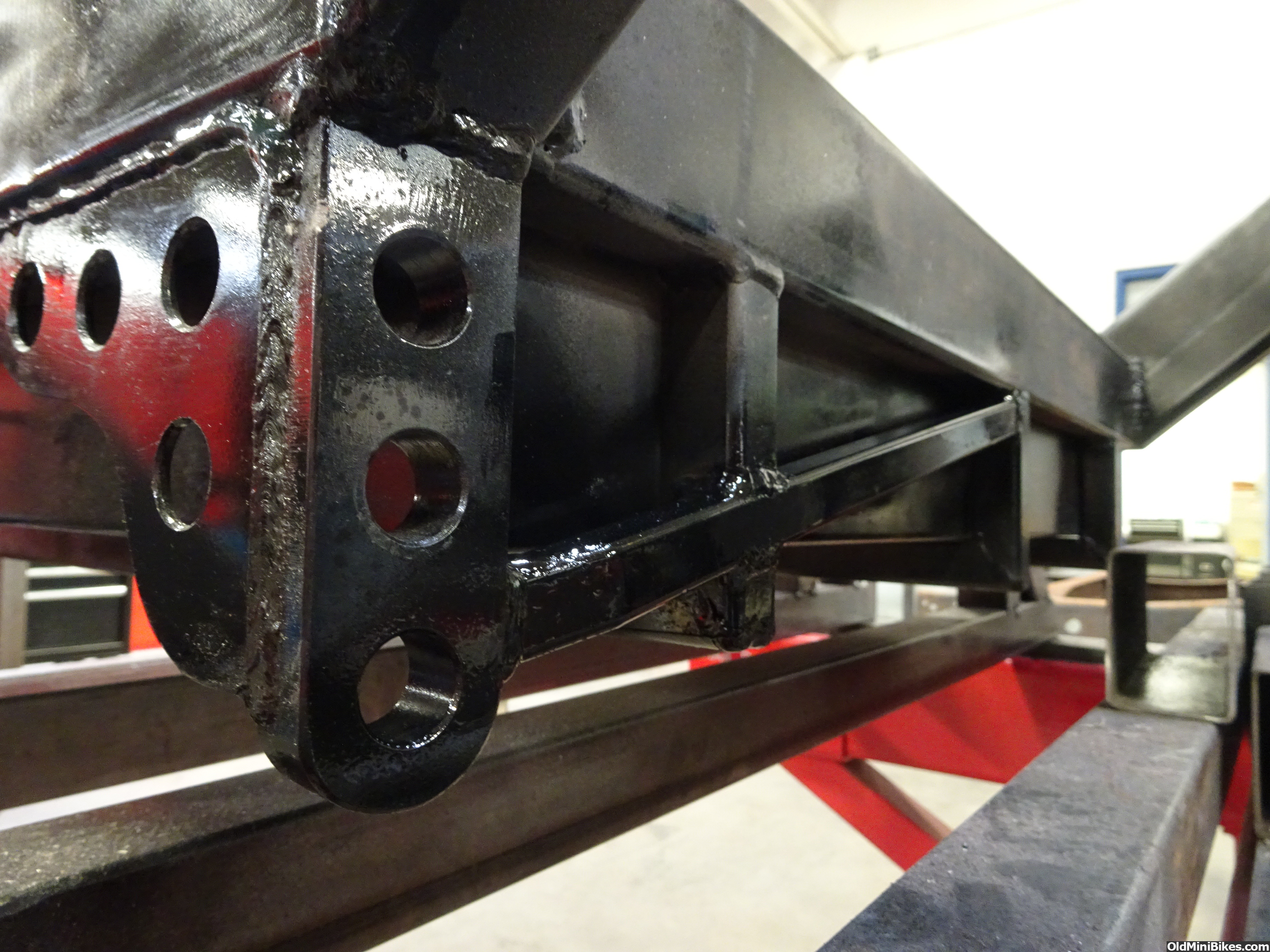
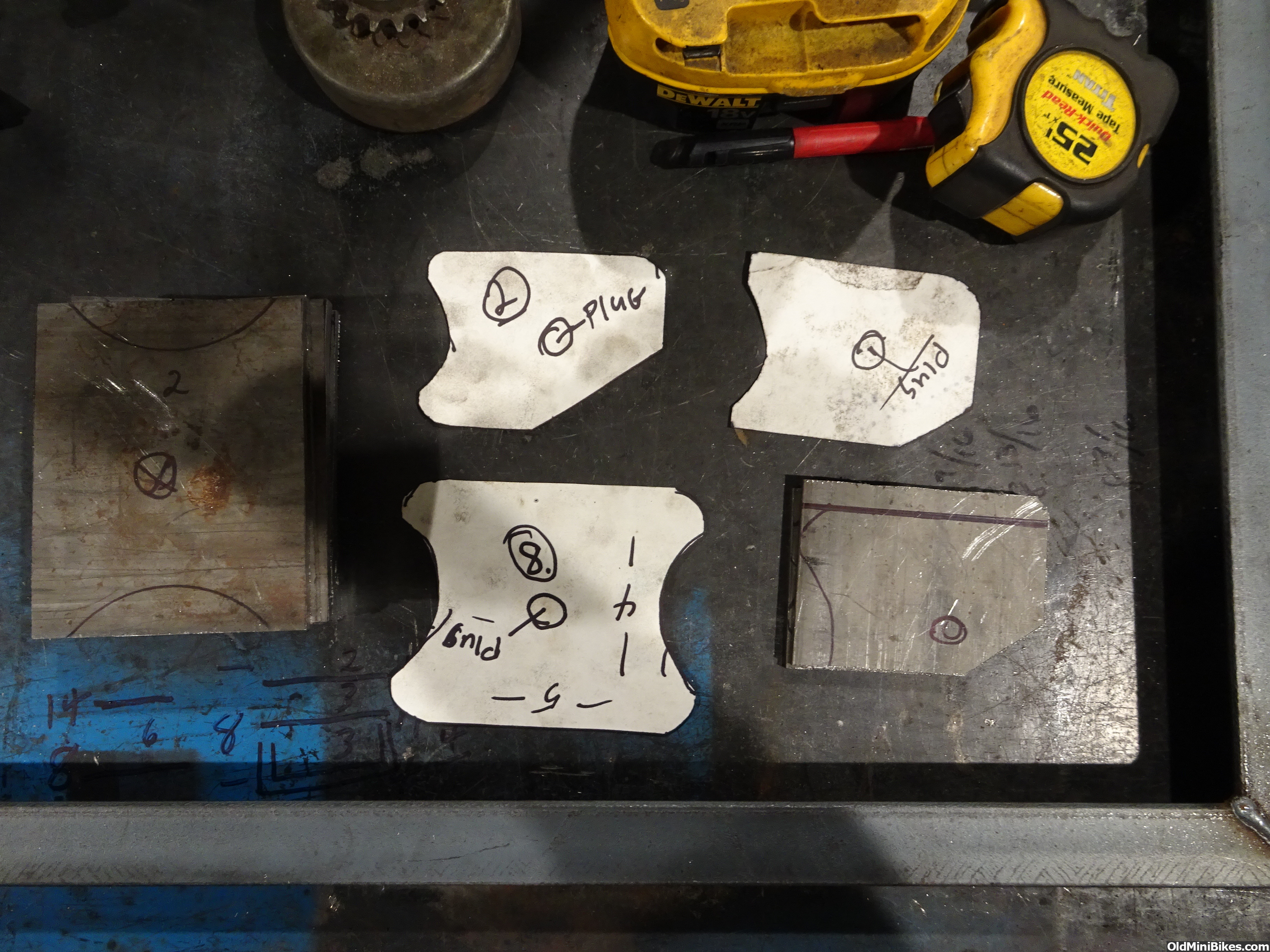
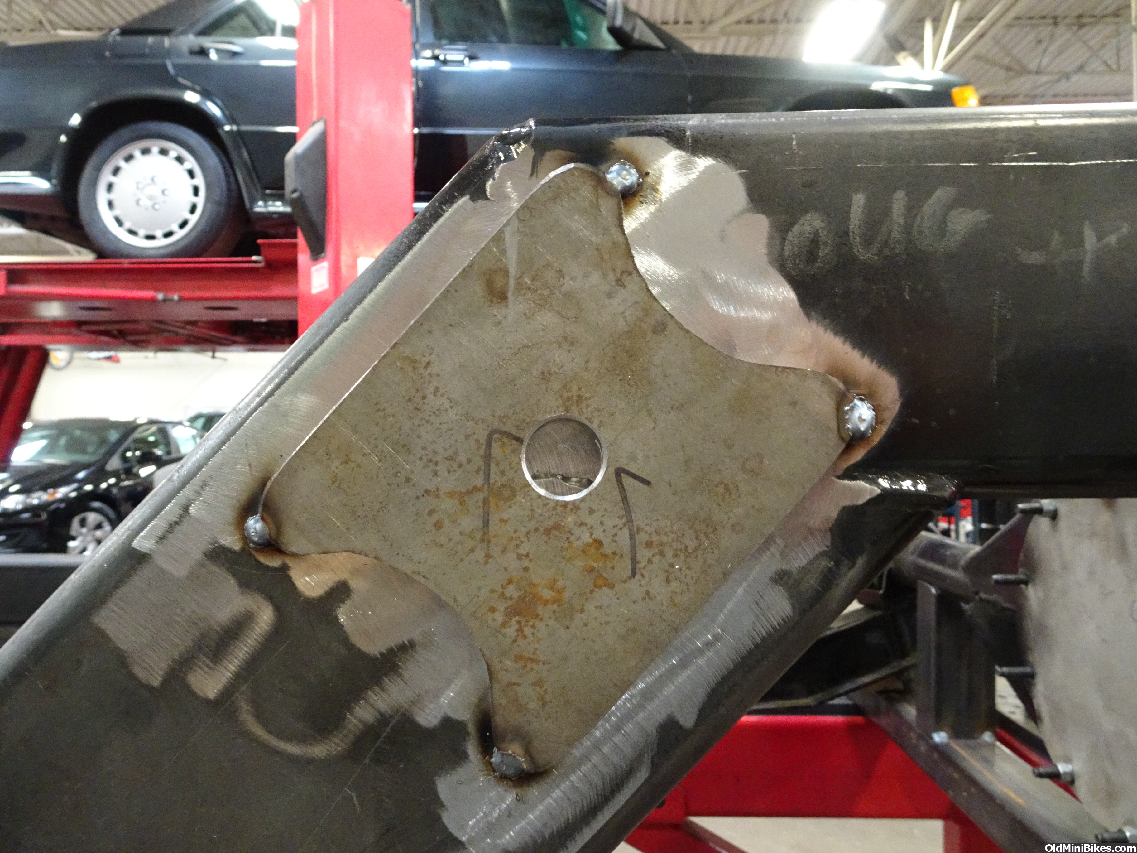
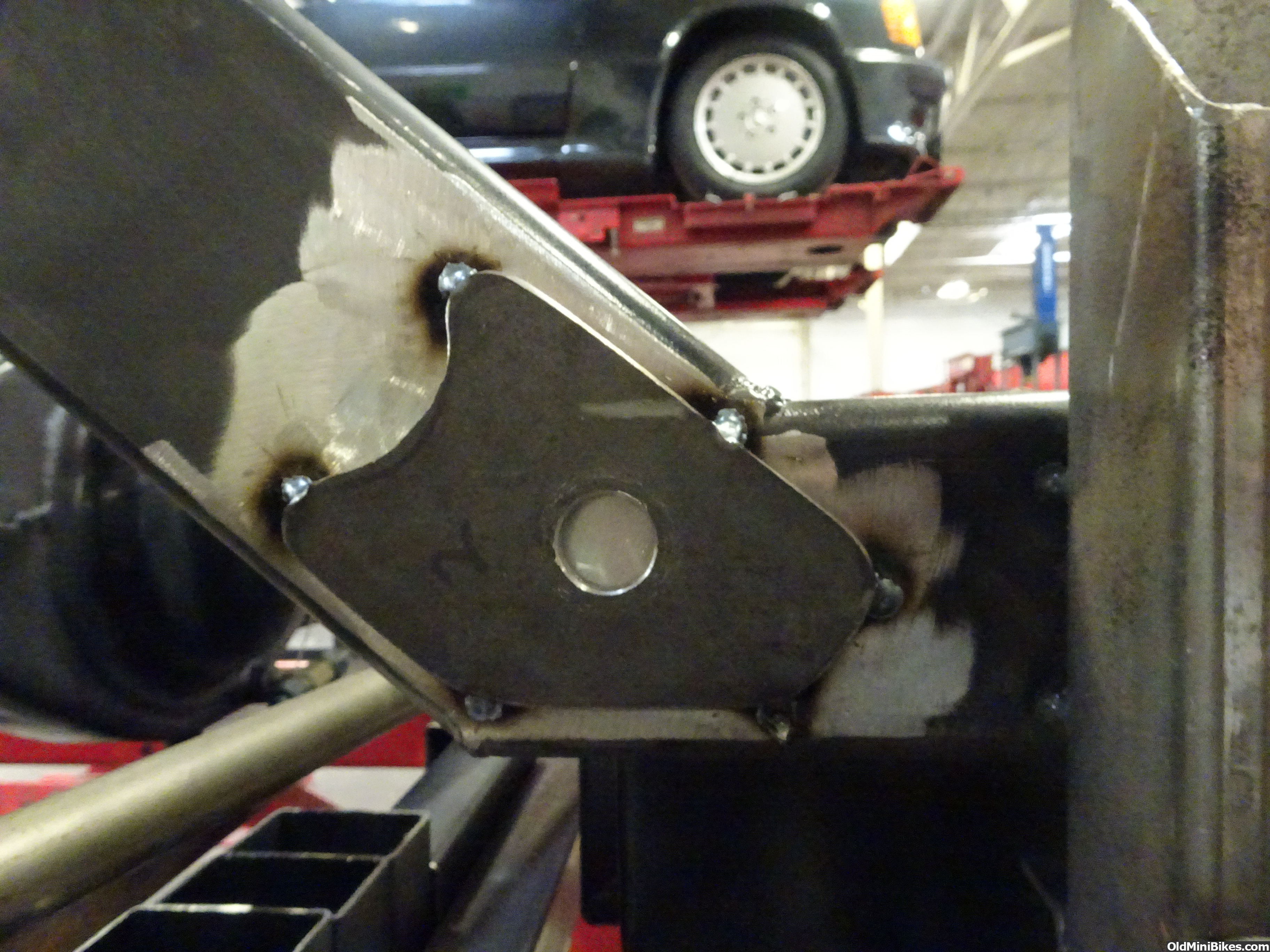
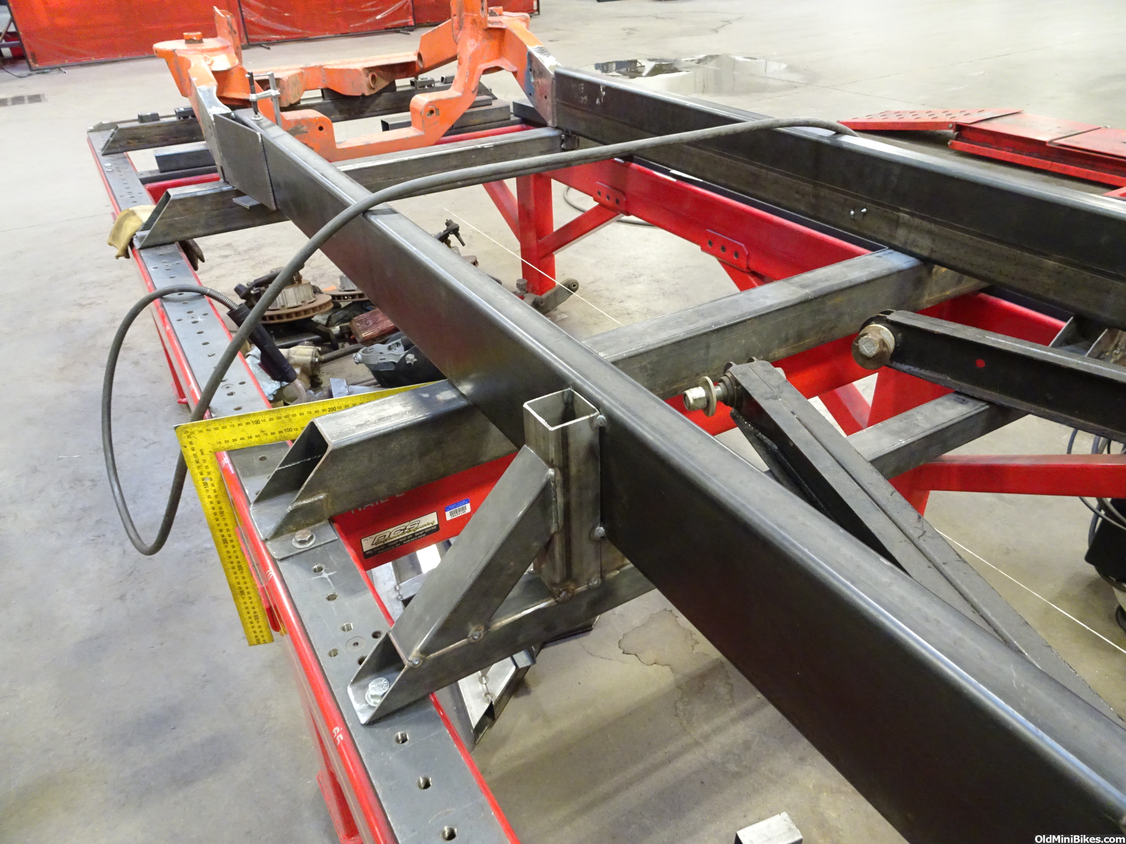
After a lengthy conversation with my friend Brent Vandervort, owner of Fatman Fabrications, I purchased 2'' x 6'' x 3/16'' tubing for the main rails. The factory Ford truck spec is 34'' outside to outside of the rails. First we centered and squared the front clip to the jig table. Then I cut and laid out the main rails. The right rail lined up with the right rail on the clip like it was meant to be that way. The left rail on the front clip is offset 2 inches outboard to increase header clearance. So the left main rail outside surface lined up with the left rail on the clip's inside surface. I cut a piece of 4'' x 6'' 3/16'' plate and made a flange that both rails could weld to. Then I added a 10'' x 6'' x 3/16'' plate to the outside to make a nice strong transition. The inside was a different story. I had a short area to work in and had to clear the steering box mounting tabs. So it is a oddly shaped piece that I had to bend in the press break. I used every available inch of surface to make as good of a transitional tie in as possible. I then plated the top with a piece of 1/8'' to tie all the pieces together.
This will be an ongoing project for me so this thread will get updated periodically.
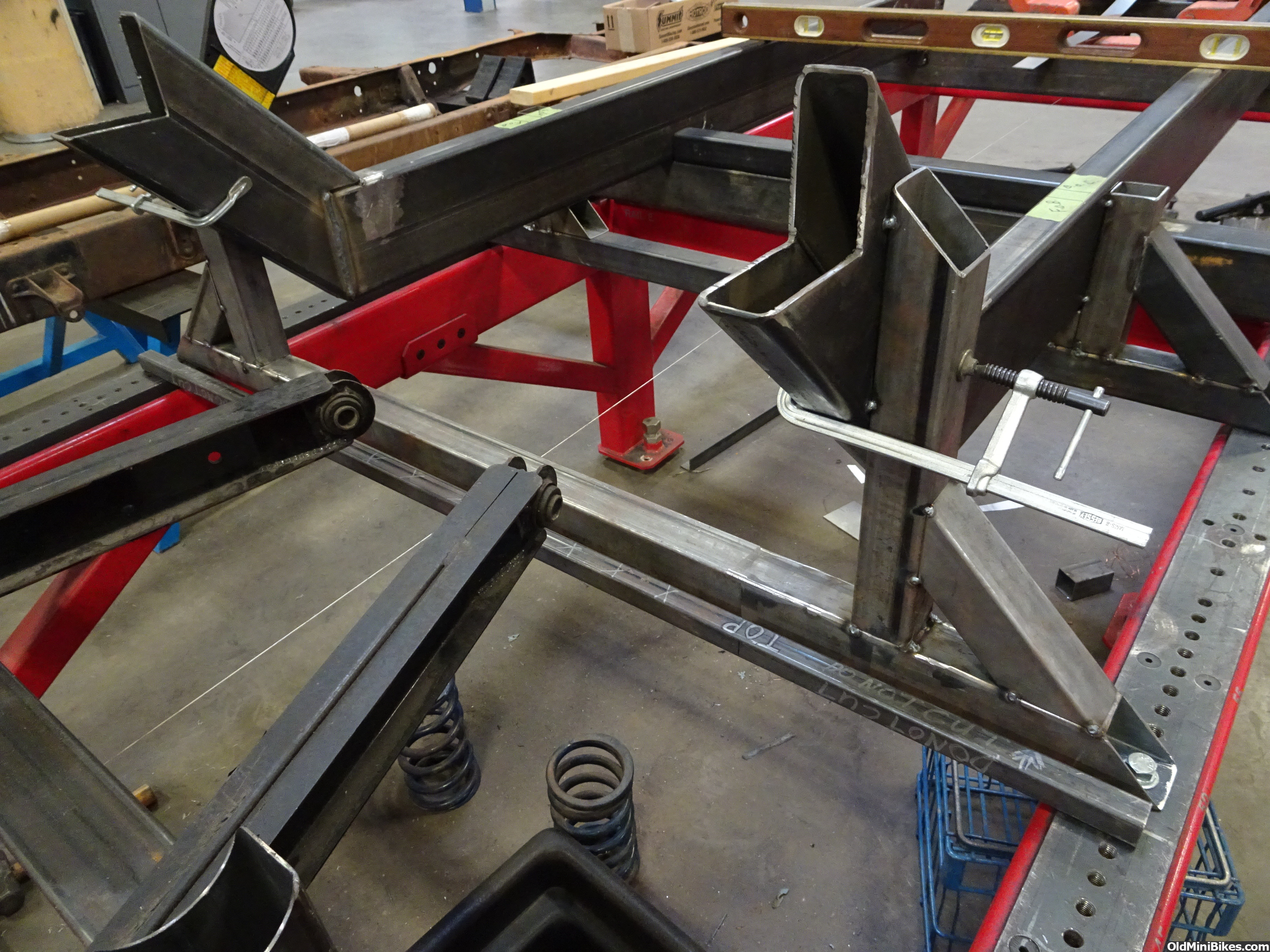
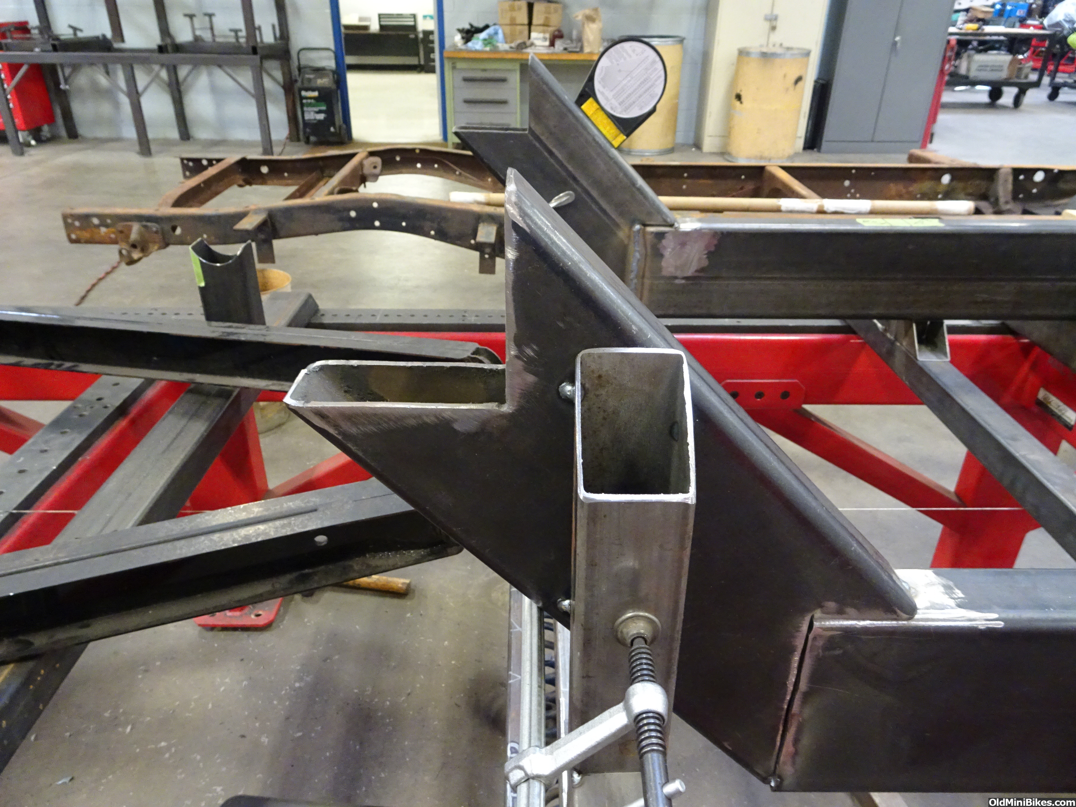
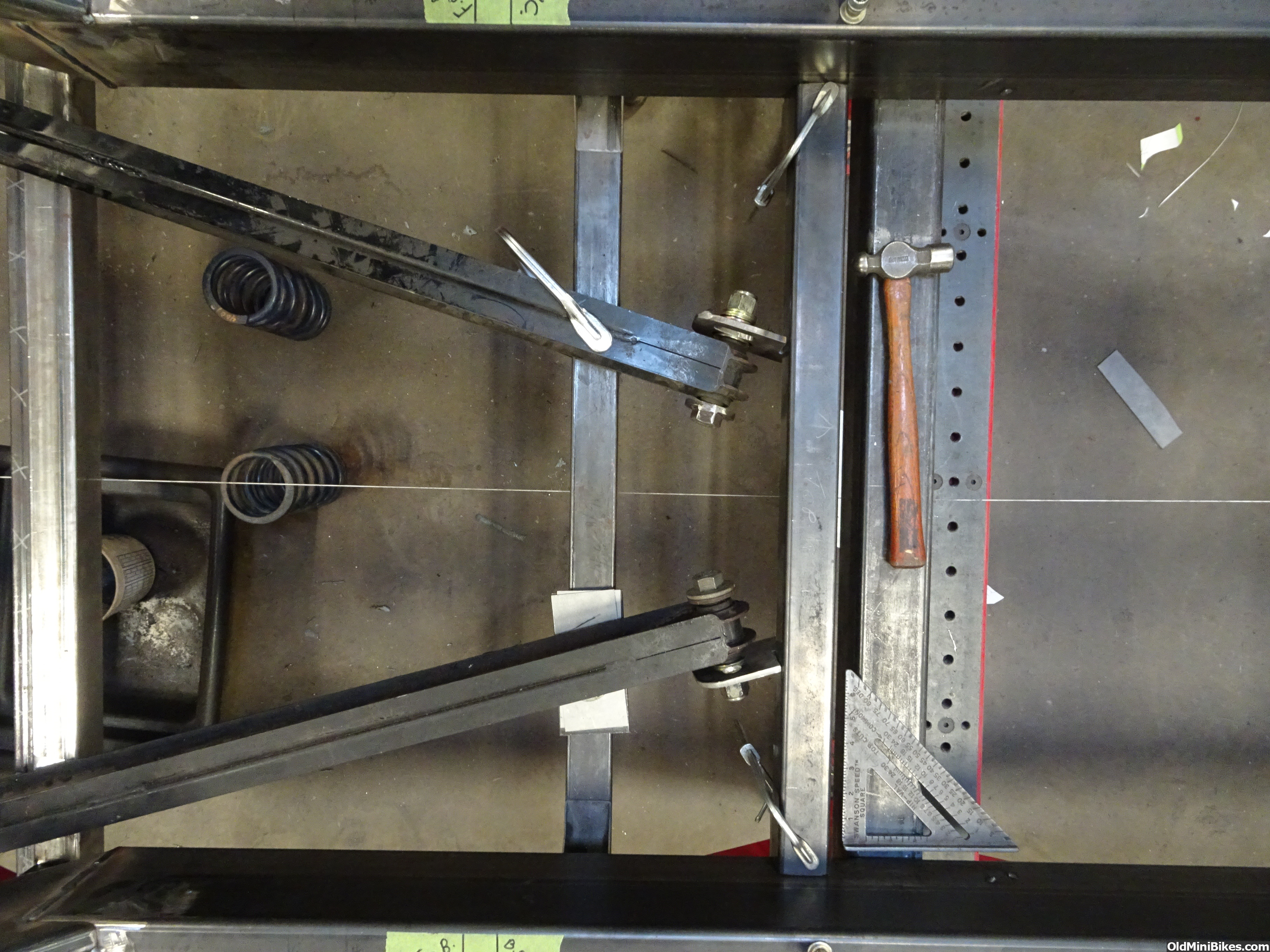
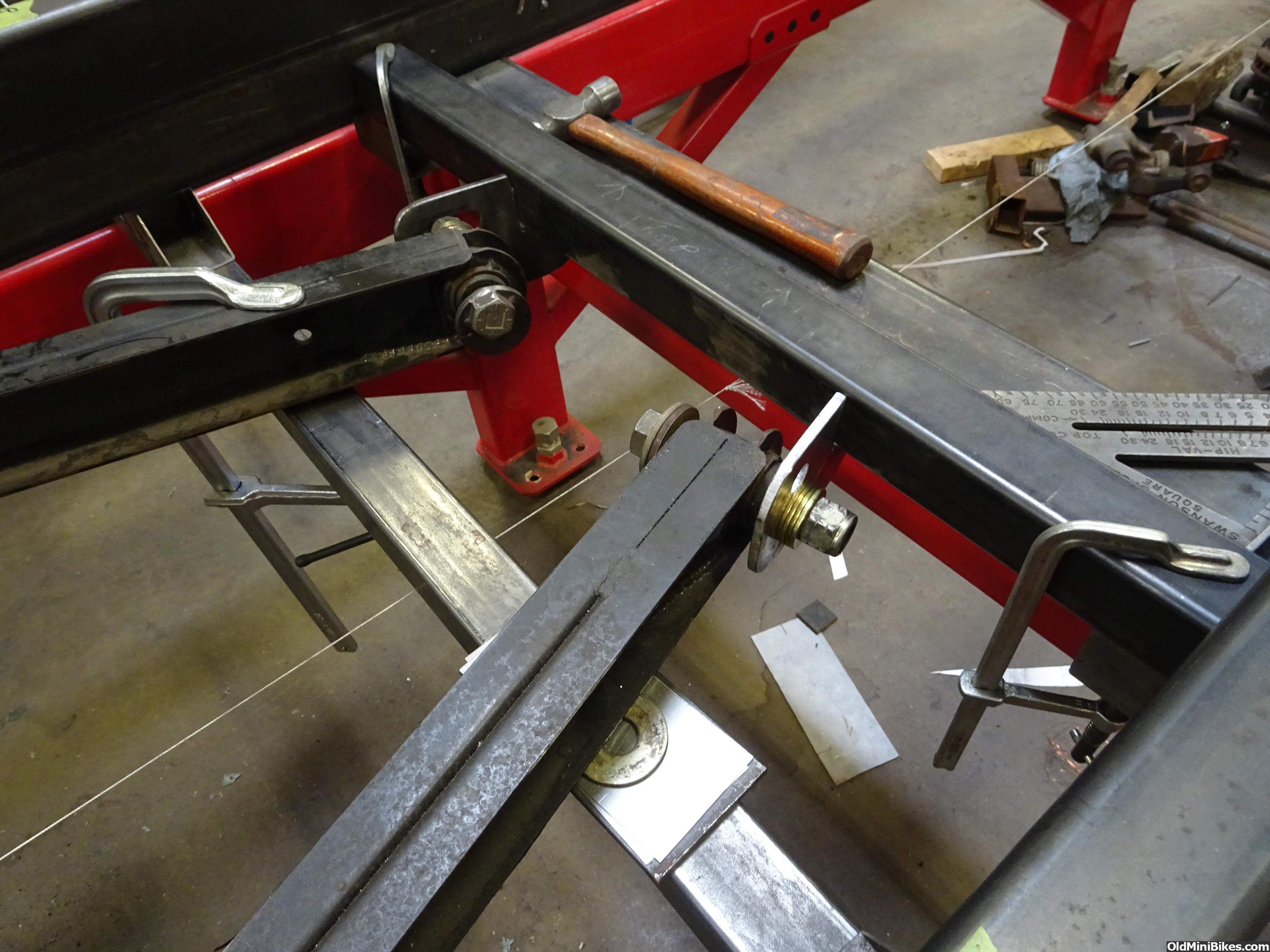
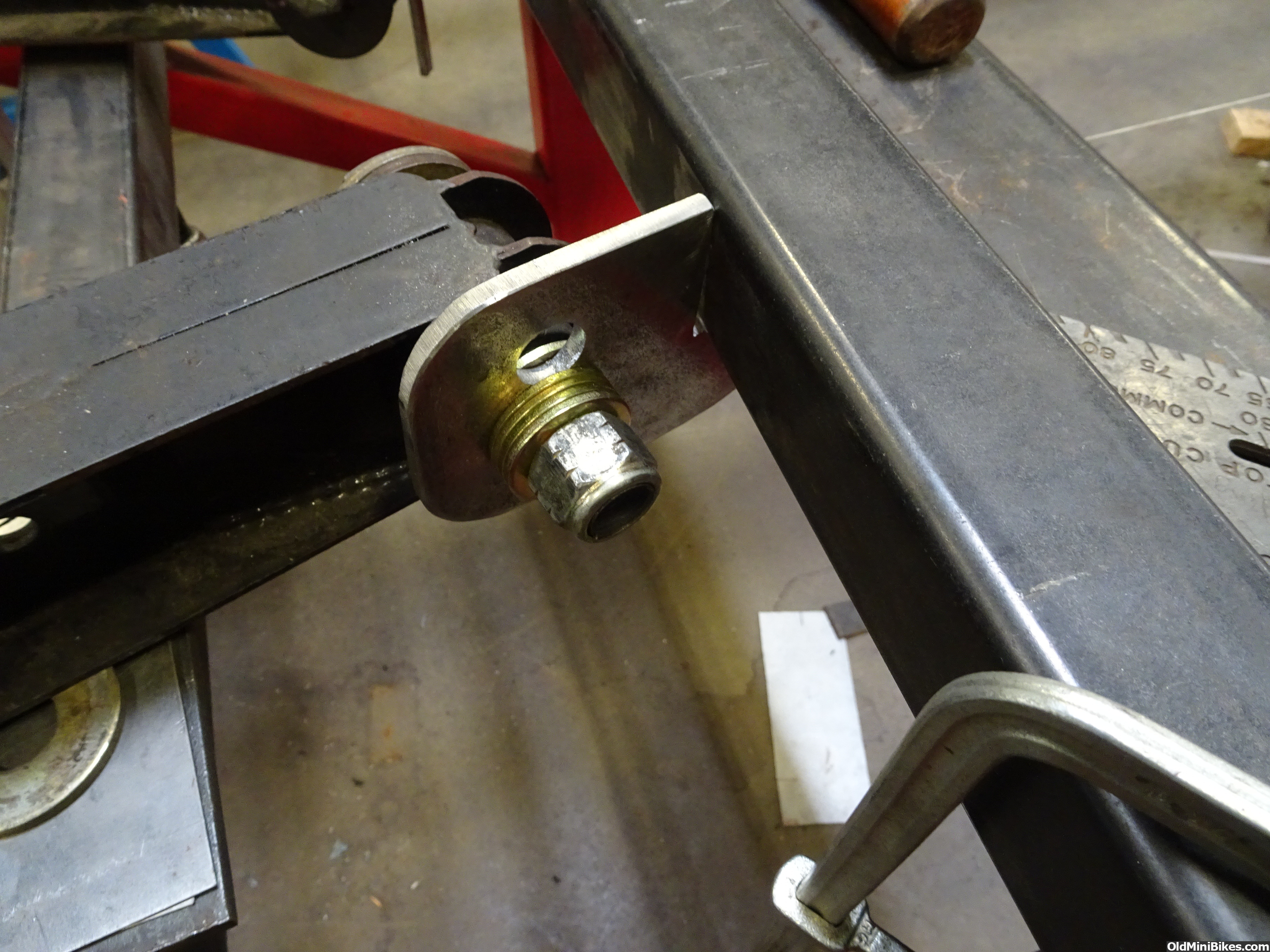
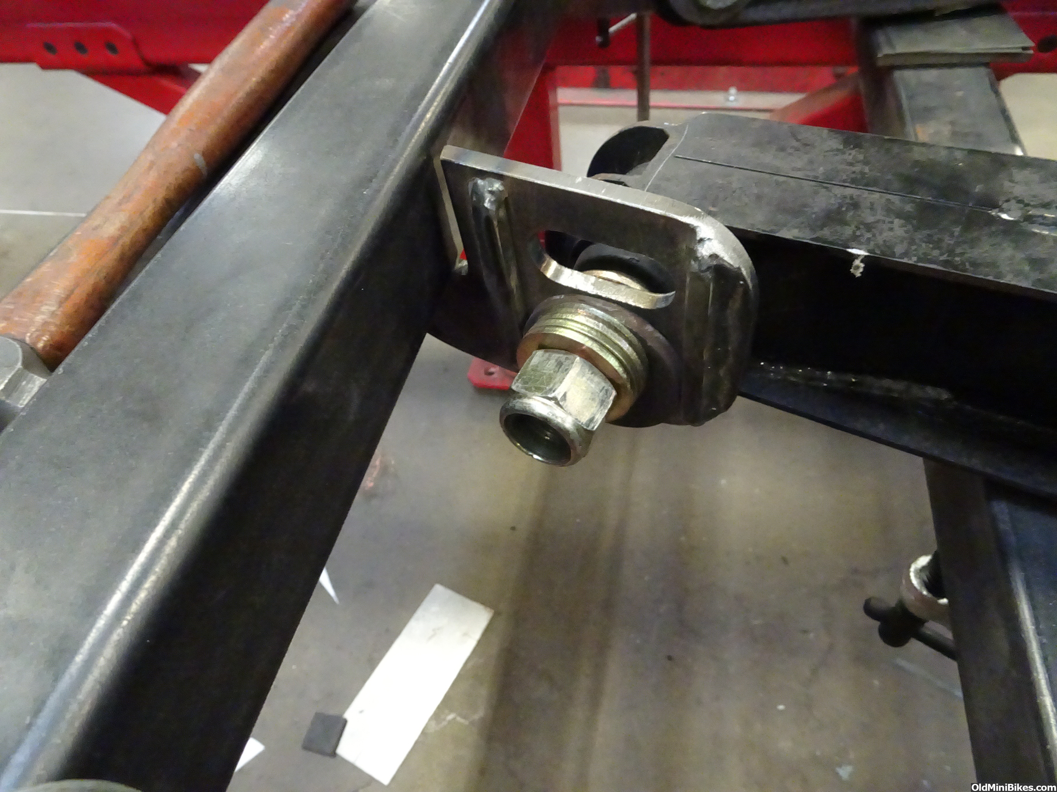
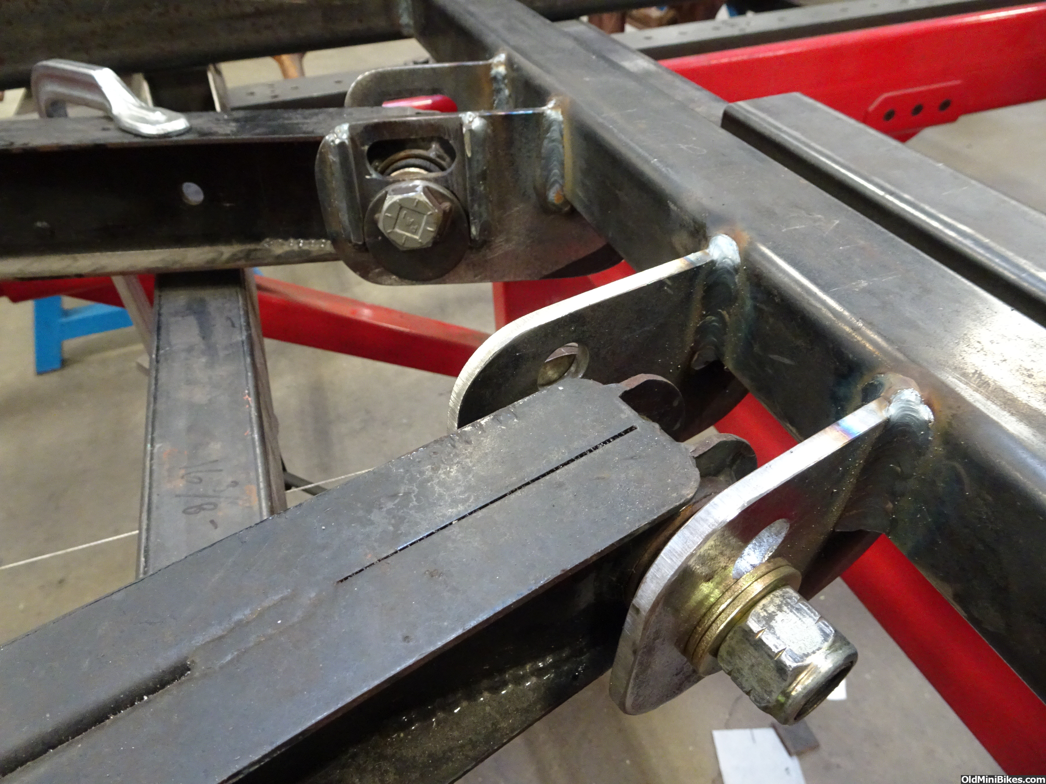
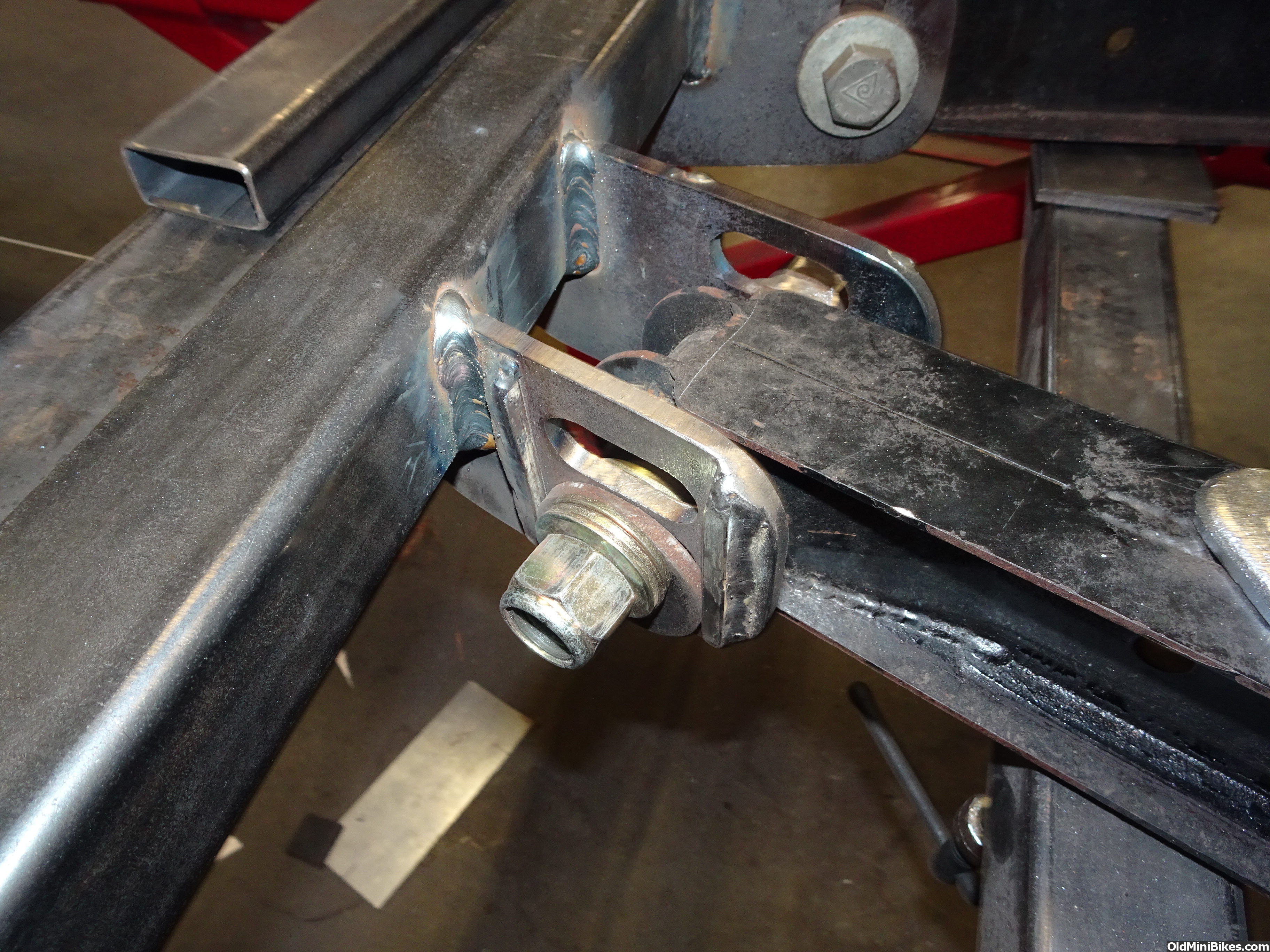
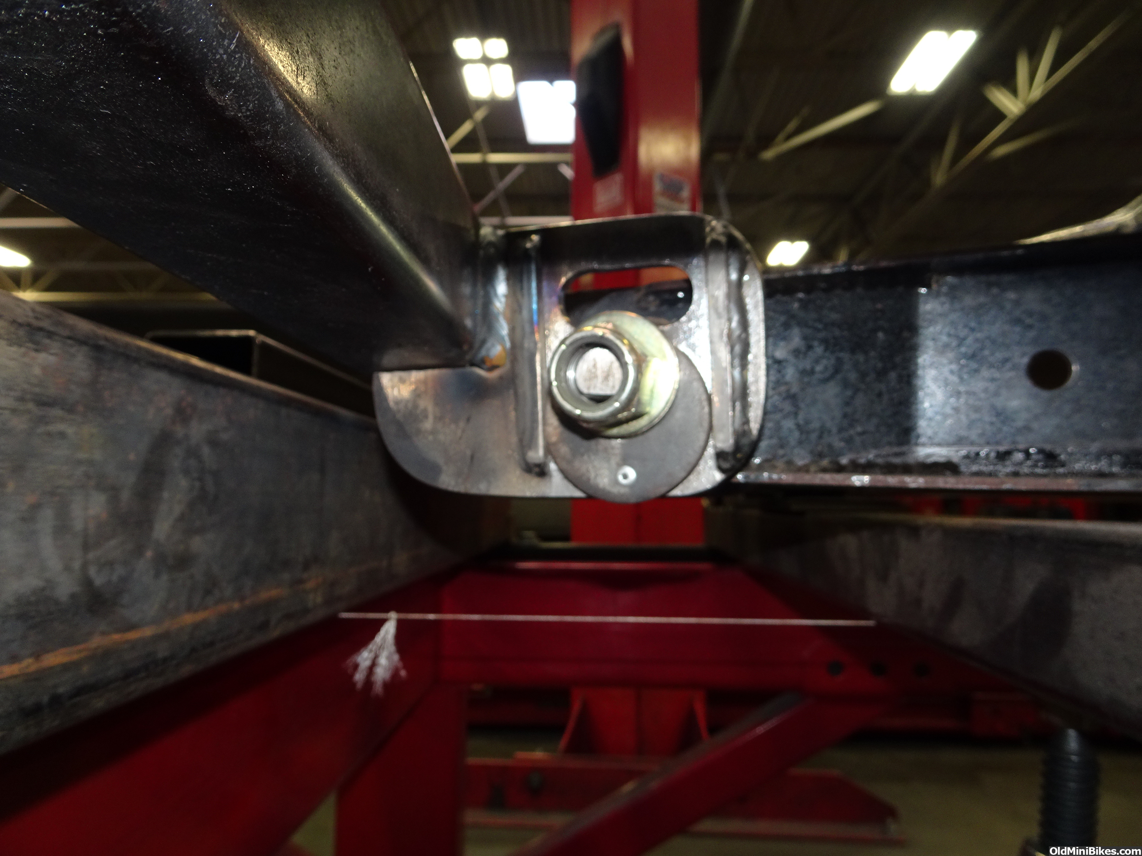
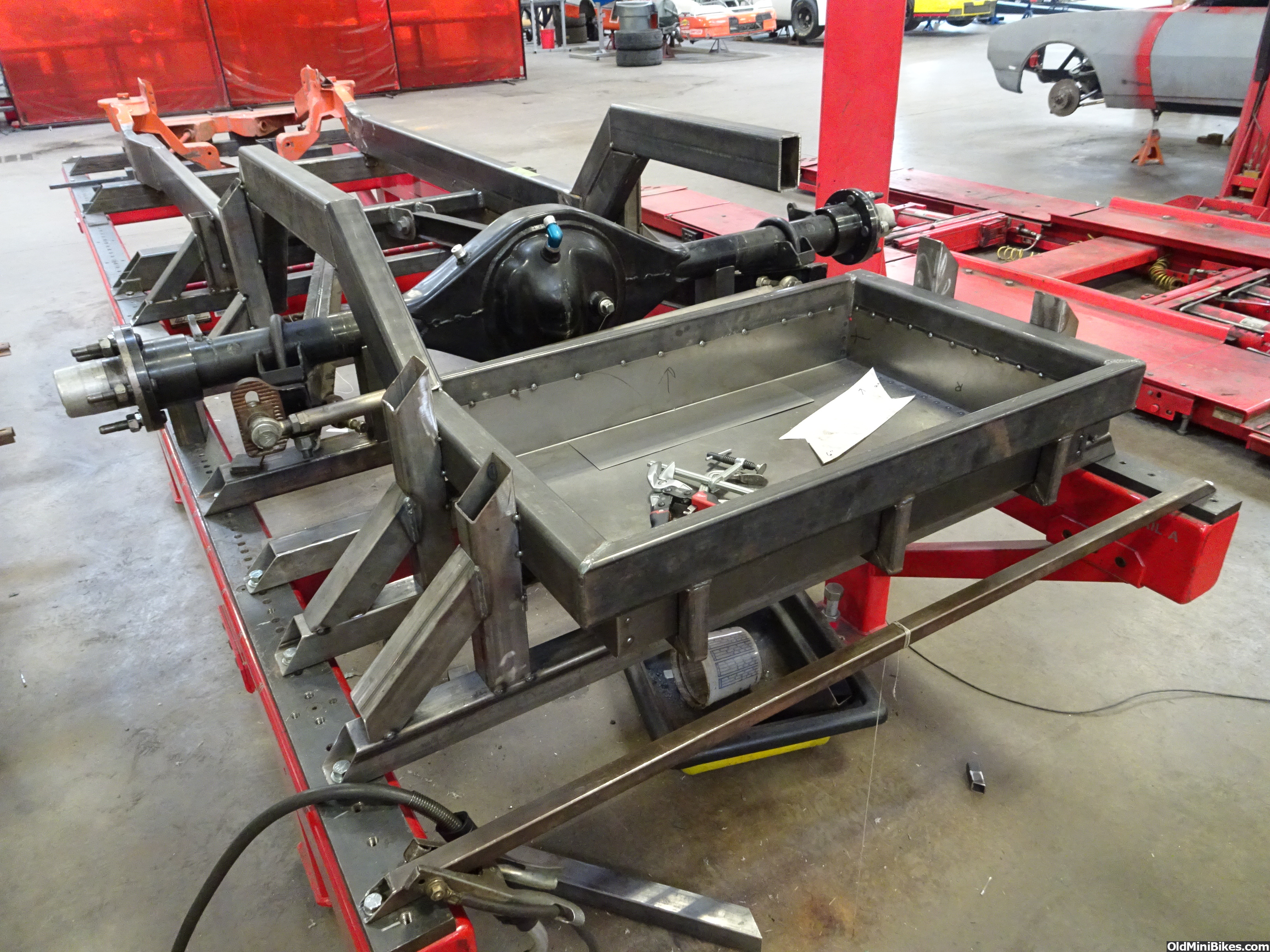
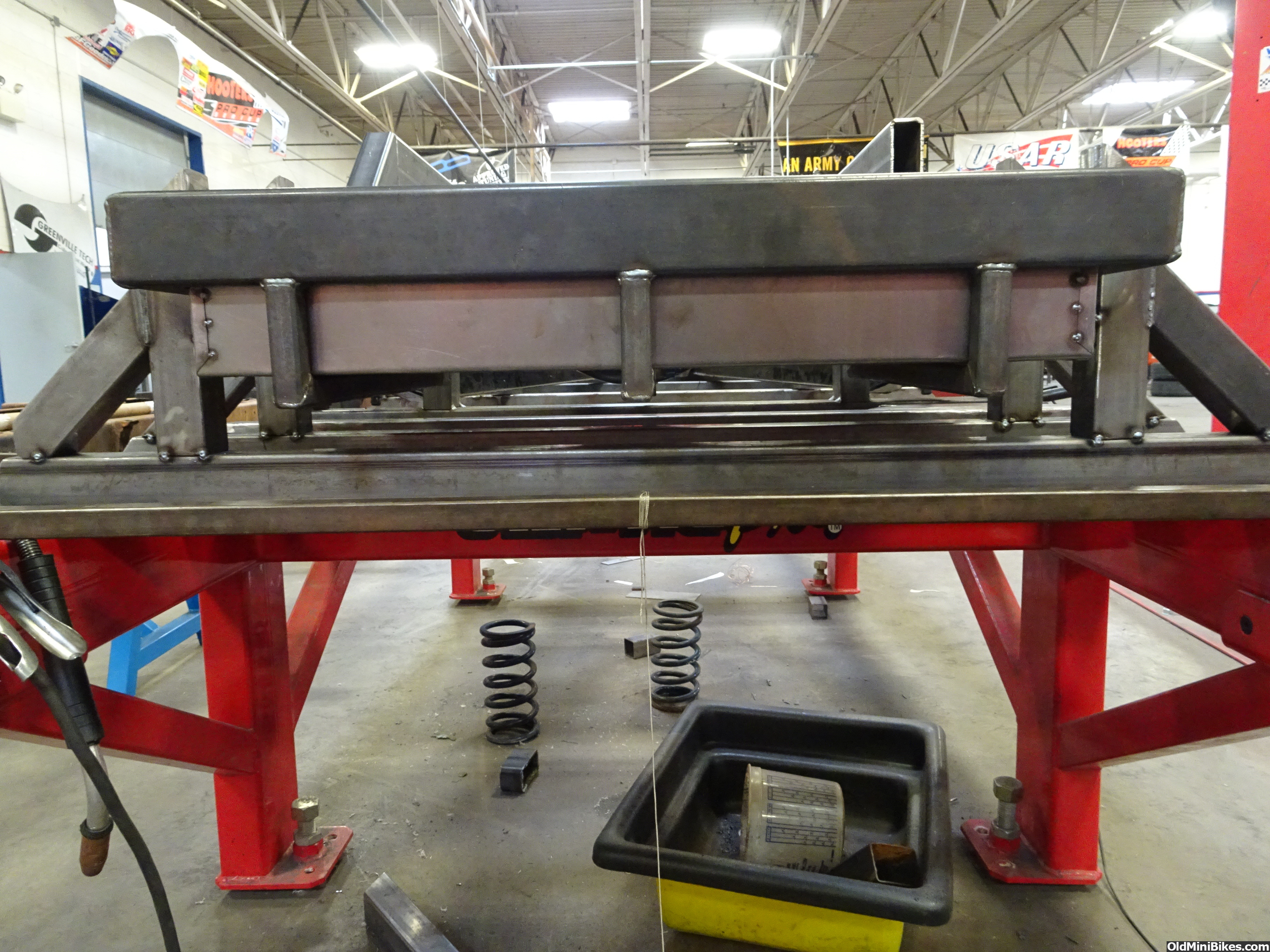
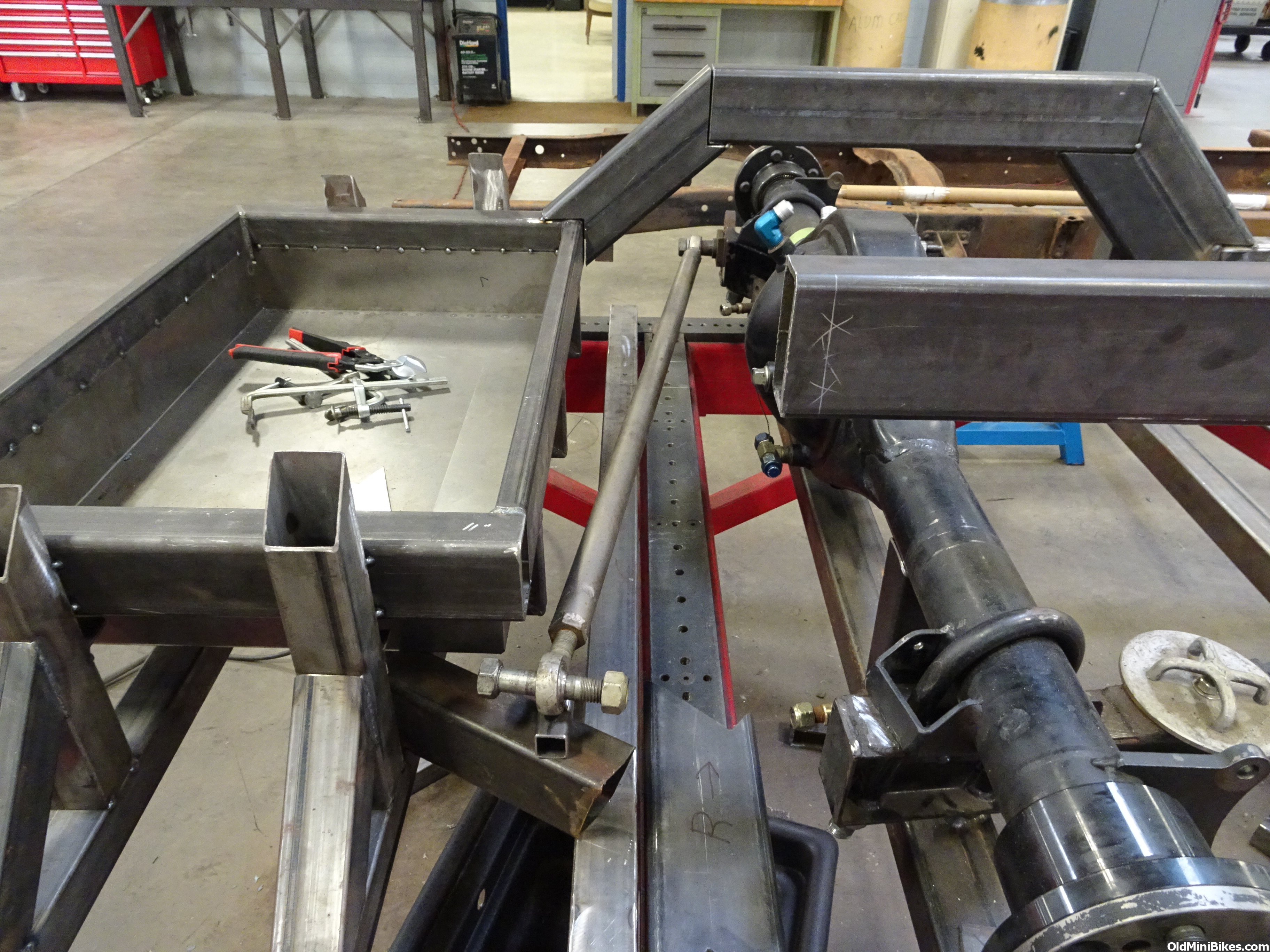
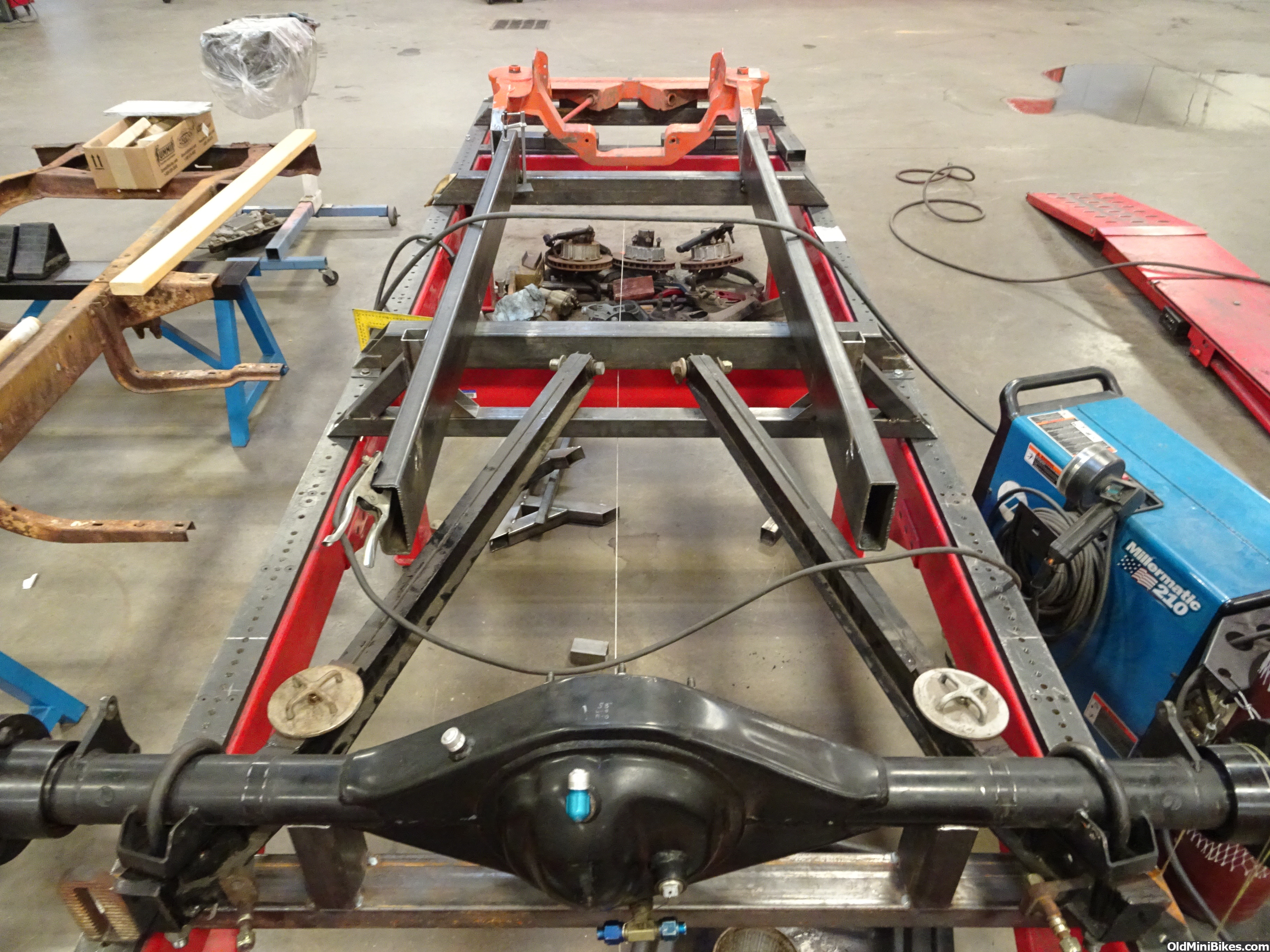
In the pics the rails are squared to the table and are welded to the crossmember uprights so that they don't move around. The front clip is welded to the crossmembers as well. I made a rear crossmember with upright saddles for the rearend housing to sit in. On one end I drilled a single hole to bolt it down to the table. On the other end I slotted the hole about 1 inch long so that it could be swung forward or back to square it to the frame and front clip. The wheelbase is set at 115'' which is 5 inches longer than stock. The rear wheels are in the stock location but the front wheels are pushed forward 5''. I will have to cut the wheel opening out of the front fenders and move it forward 4'' to center the tire in the opening. The factory setup has the tires 1'' behind the center of the fender opening... This drastically improves the look of the fat fendered Effies. The leading part of the front fenders is larger than the trailing part. By moving the opening forward you reverse this front heaviness giving it a look of forward motion just sitting still.
Here are some pics of the progress.
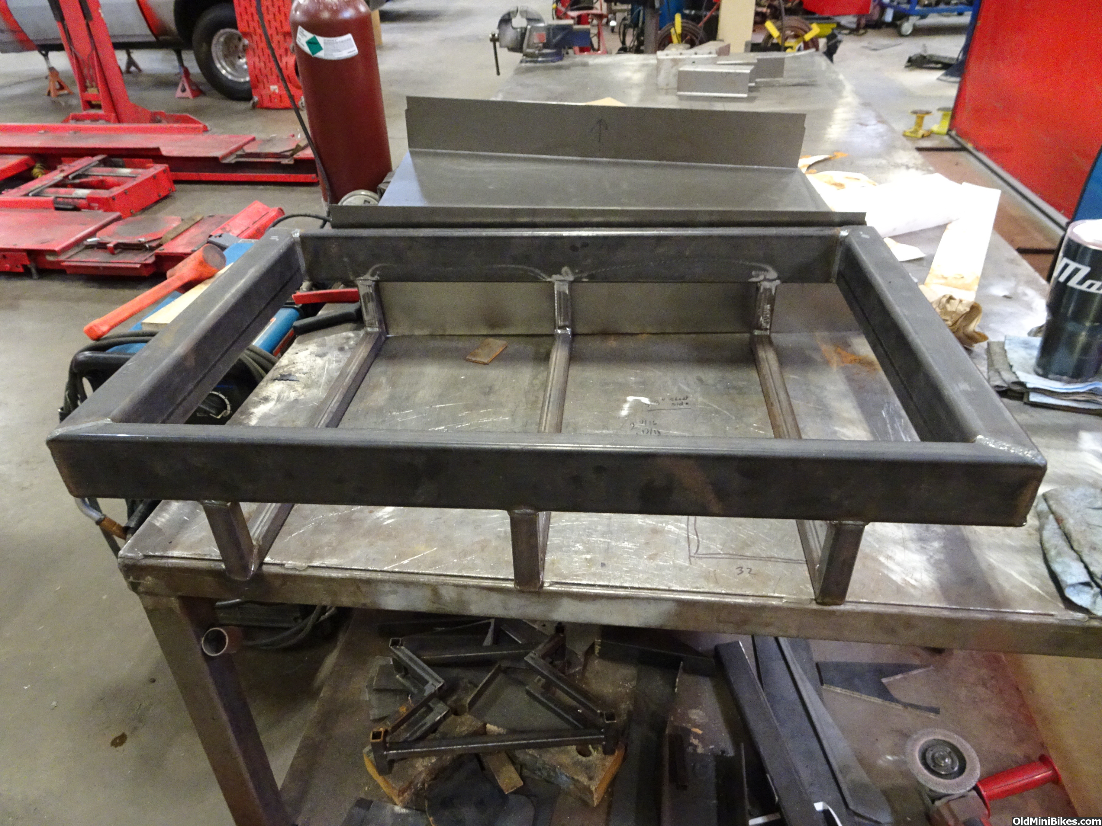
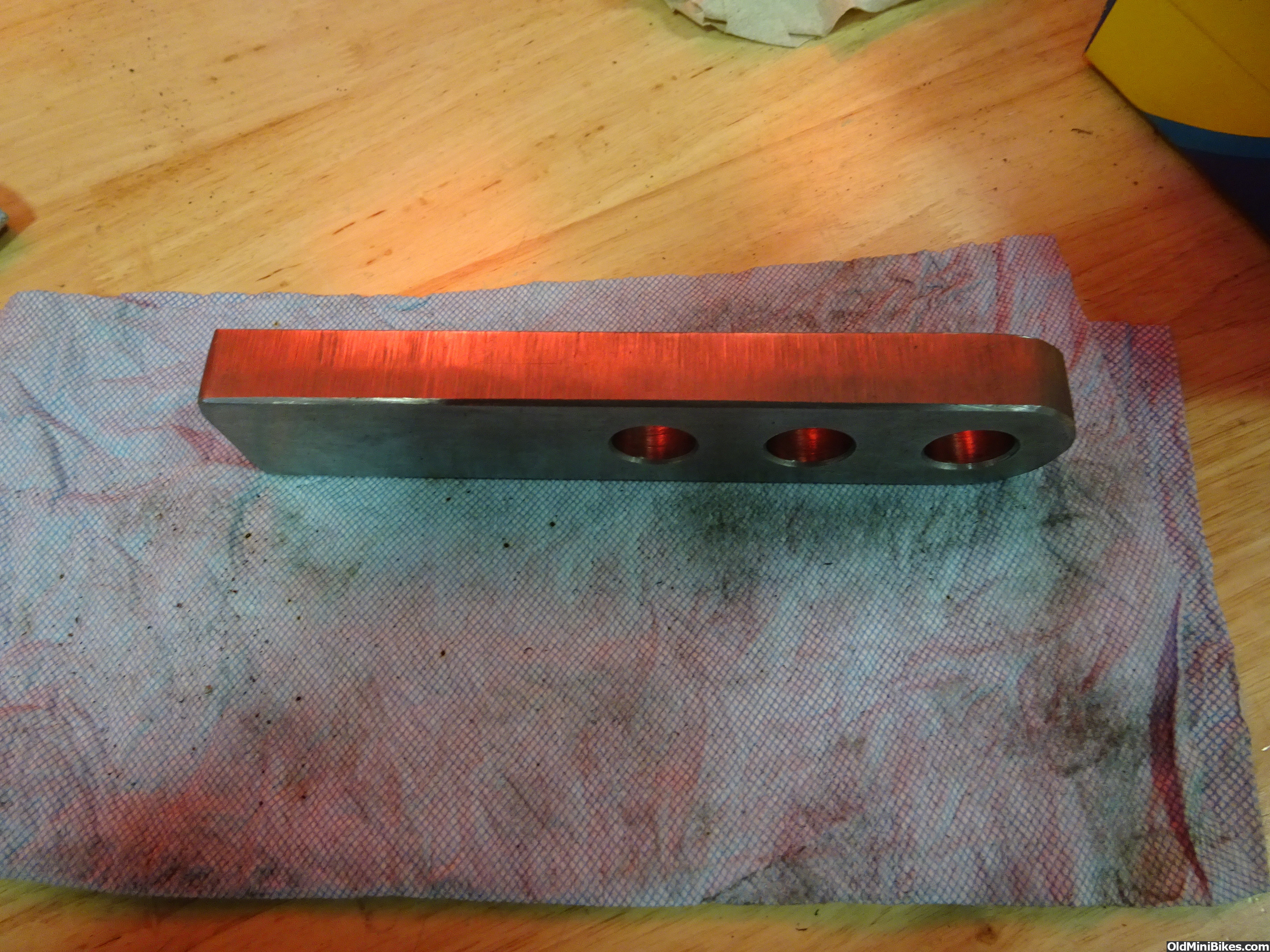
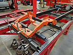
Humble beginnings

Starting
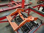
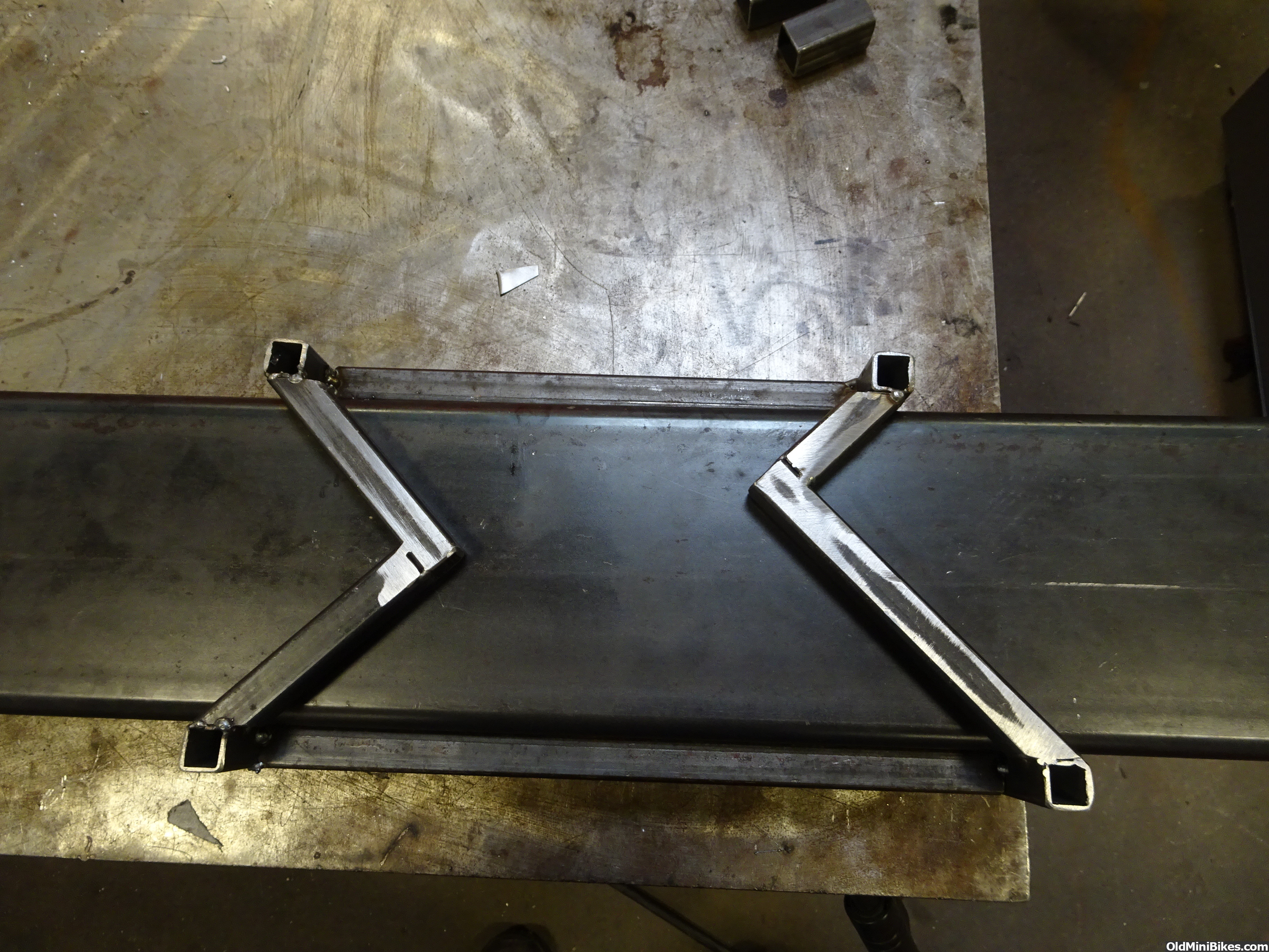
Squared and tabbed to the table.
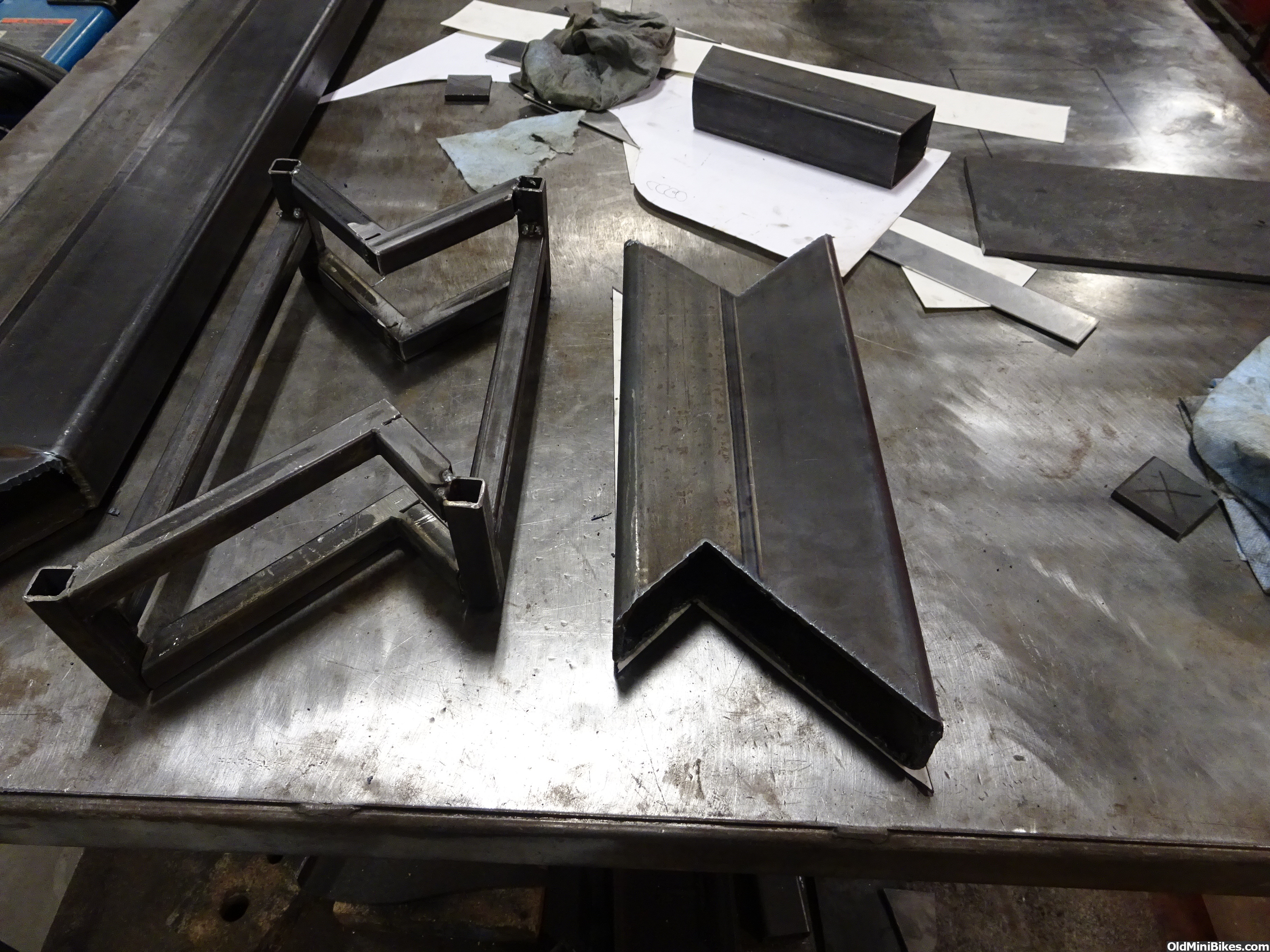
Main rails laid out and lined up

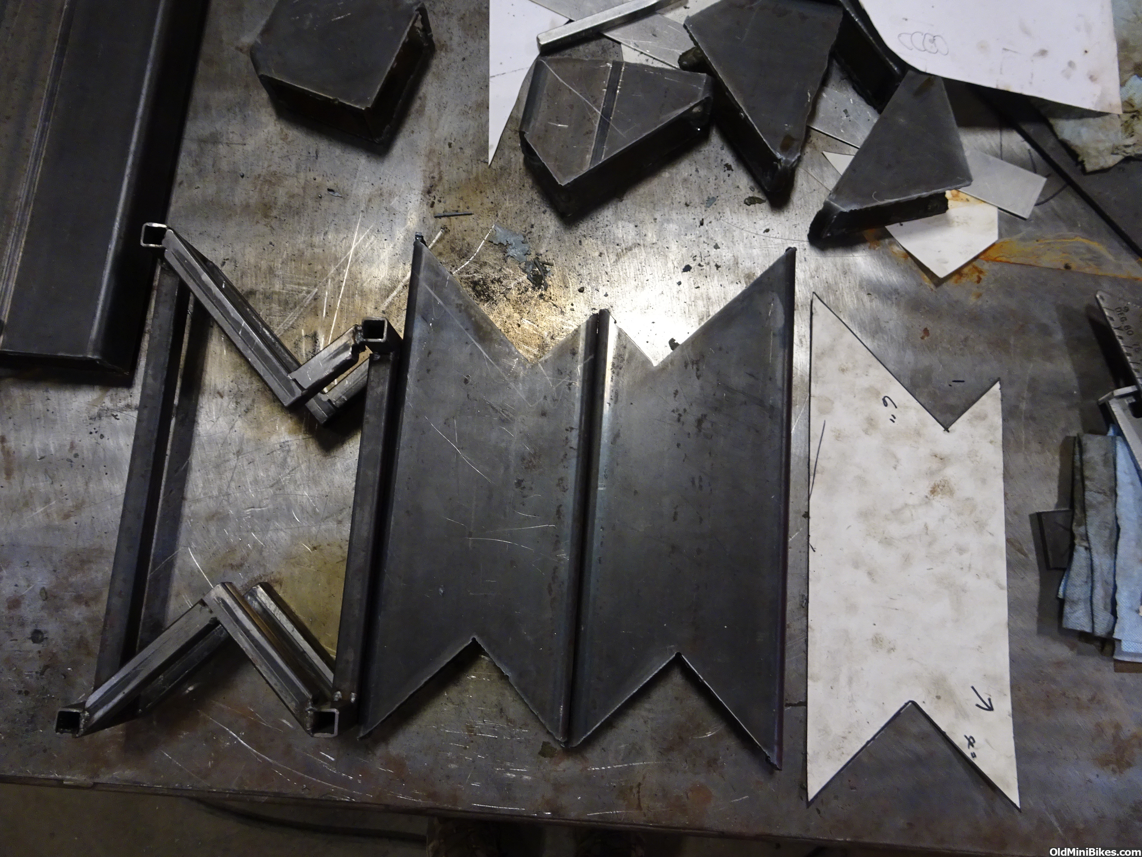
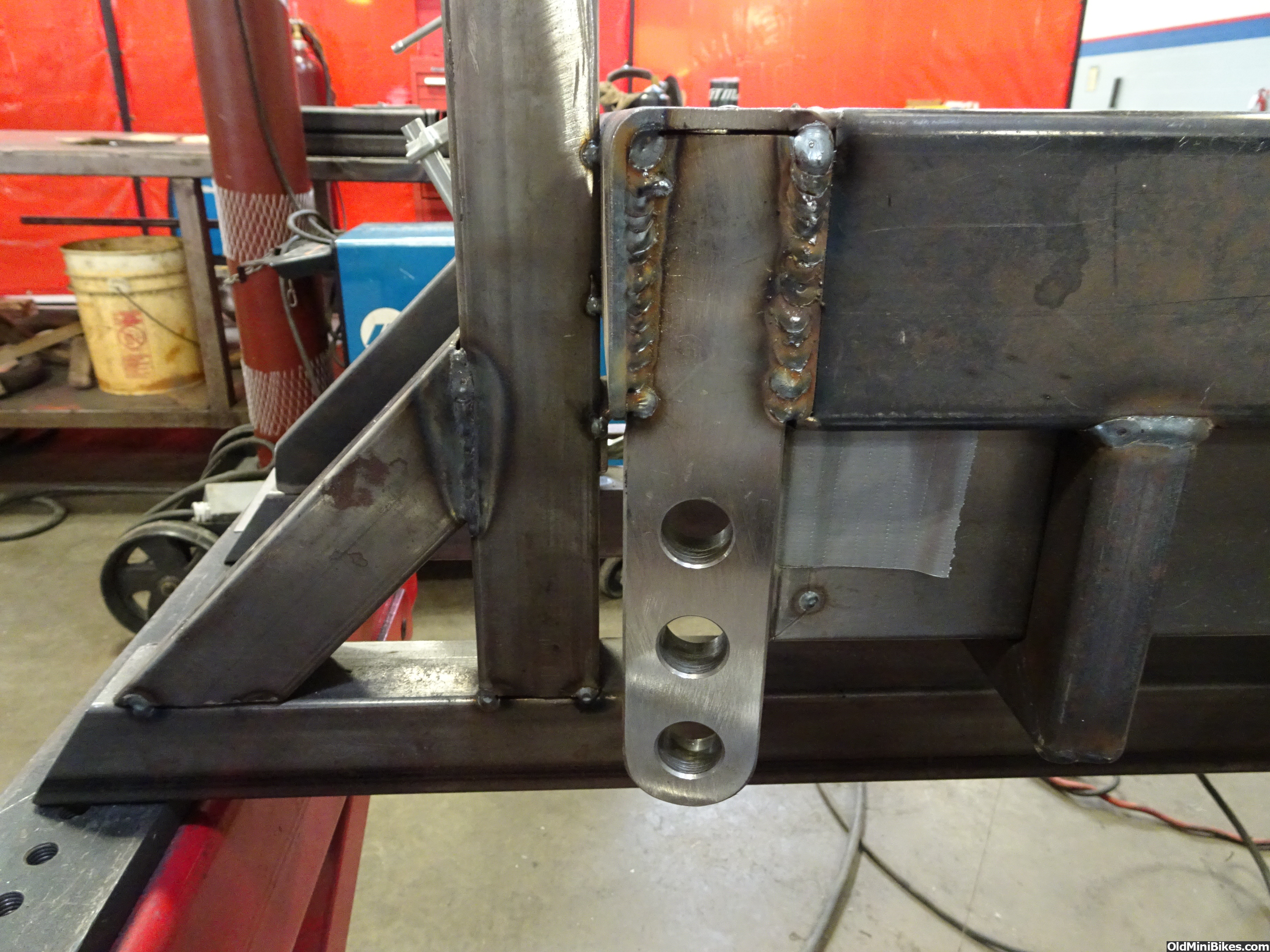
Main rails welded to the crossmember uprights and front clip. This shows the offset in the steering box area

This is a frame that is going under my personal 1956 F-100.
Just a little history on the front snout. I am using a fabricated front snout that I picked up back in the late 90's. It is a Bill Funderburk design fabricated snout. Funderburk worked at H&M from the middle 60's into the 70's then went on to build chassis for his self. These are based on a 1965 Galaxie "rear steer" frame. They were the dominant chassis design until someone (Bobby Allison gets the credit in most circles) came up with the GM "front steer" chassis. The rear steers down fall was that it picked up a push as the race progressed. You had to set them up with a lot of static toe in so that they wouldn't toe out later in the race. When the front steer cars didn't develop a push later in the race they were the cure to that ill handling problem.
I am building this to a Road Race chassis spec so that it will be a good street setup. The road race setups were equal right and left. The left turn chassis is skewed to turn left the best. I had to search for about 3 months to find a 9'' rear end housing that didn't have any camber in the tubes. Steve, the school instructor, had almost all of the front end components. Big brakes with 6 piston calipers, A-arms and steering that included a 16 to 1 Sweet Mfg power steering steering box. Would have liked for it to have been a 14 to 1 but the price was right.
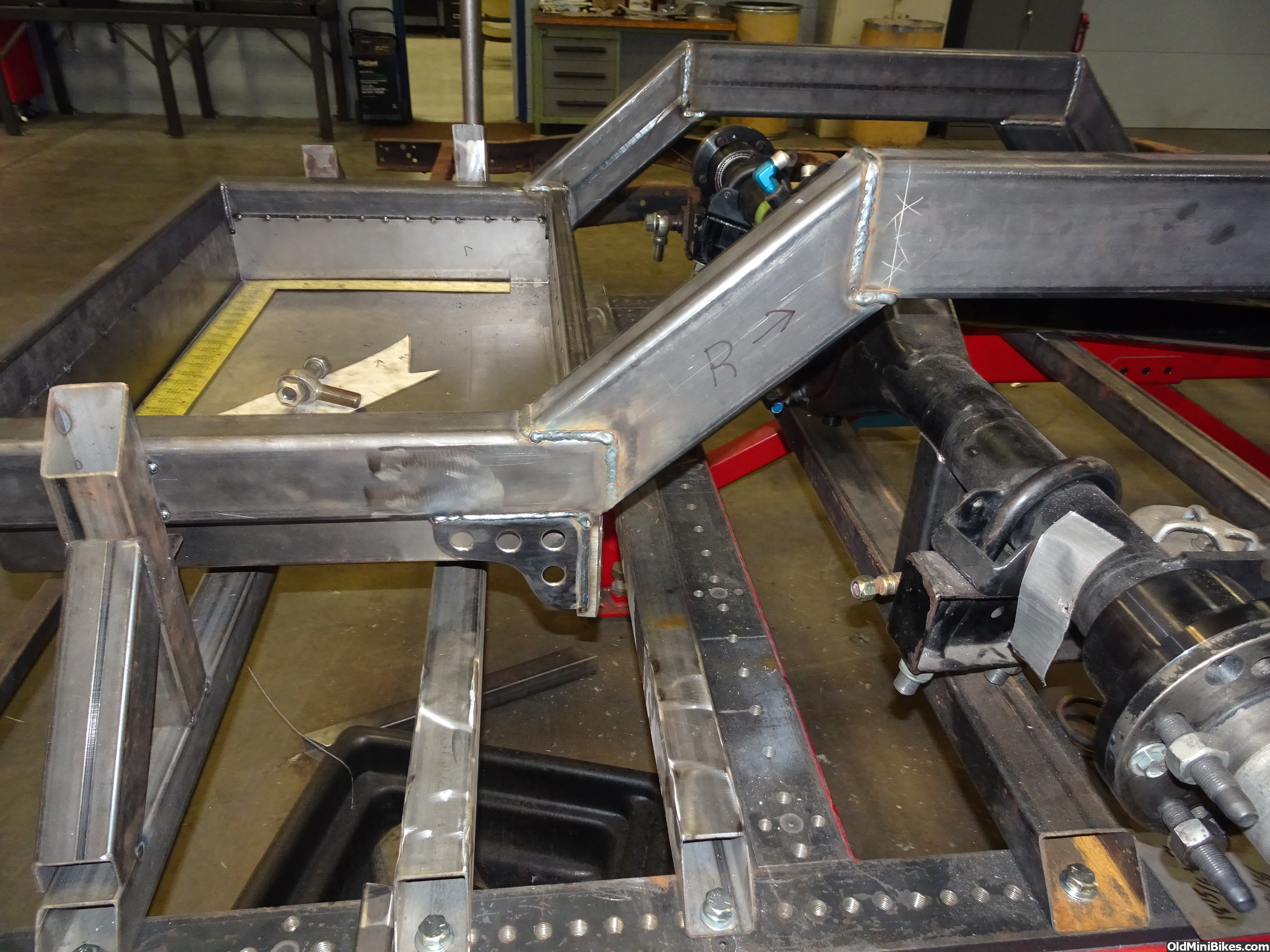
After a lengthy conversation with my friend Brent Vandervort, owner of Fatman Fabrications, I purchased 2'' x 6'' x 3/16'' tubing for the main rails. The factory Ford truck spec is 34'' outside to outside of the rails. First we centered and squared the front clip to the jig table. Then I cut and laid out the main rails. The right rail lined up with the right rail on the clip like it was meant to be that way. The left rail on the front clip is offset 2 inches outboard to increase header clearance. So the left main rail outside surface lined up with the left rail on the clip's inside surface. I cut a piece of 4'' x 6'' 3/16'' plate and made a flange that both rails could weld to. Then I added a 10'' x 6'' x 3/16'' plate to the outside to make a nice strong transition. The inside was a different story. I had a short area to work in and had to clear the steering box mounting tabs. So it is a oddly shaped piece that I had to bend in the press break. I used every available inch of surface to make as good of a transitional tie in as possible. I then plated the top with a piece of 1/8'' to tie all the pieces together.
This will be an ongoing project for me so this thread will get updated periodically.
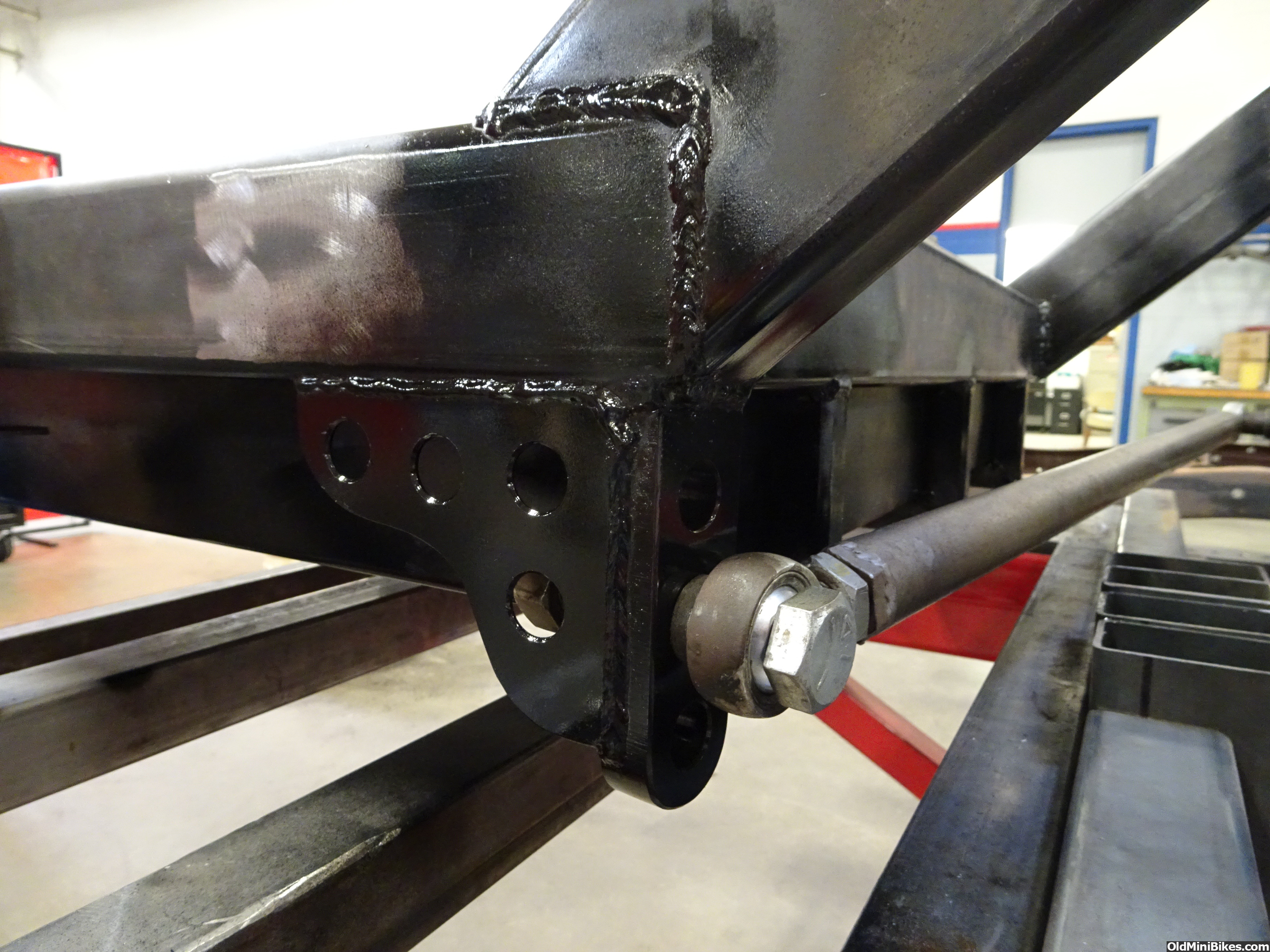
In the pics the rails are squared to the table and are welded to the crossmember uprights so that they don't move around. The front clip is welded to the crossmembers as well. I made a rear crossmember with upright saddles for the rearend housing to sit in. On one end I drilled a single hole to bolt it down to the table. On the other end I slotted the hole about 1 inch long so that it could be swung forward or back to square it to the frame and front clip. The wheelbase is set at 115'' which is 5 inches longer than stock. The rear wheels are in the stock location but the front wheels are pushed forward 5''. I will have to cut the wheel opening out of the front fenders and move it forward 4'' to center the tire in the opening. The factory setup has the tires 1'' behind the center of the fender opening... This drastically improves the look of the fat fendered Effies. The leading part of the front fenders is larger than the trailing part. By moving the opening forward you reverse this front heaviness giving it a look of forward motion just sitting still.
Here are some pics of the progress.
Humble beginnings
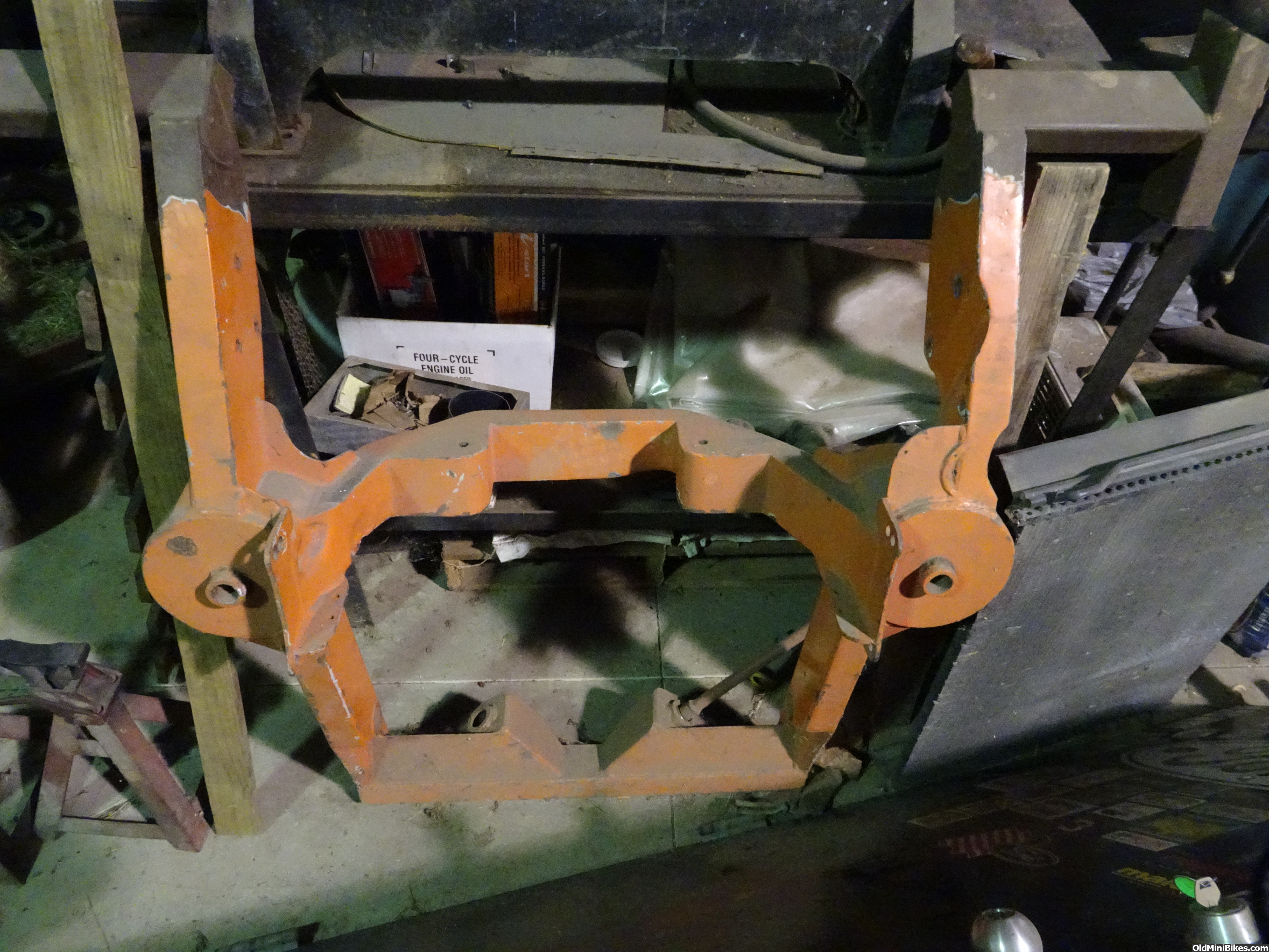
Starting

Squared and tabbed to the table.

Main rails laid out and lined up
Main rails welded to the crossmember uprights and front clip. This shows the offset in the steering box area
Last edited: