This will work on any minibike. How you do it and what you want it to look like is your choice. This I did to my AM Hawg Ty.
It was inexpensive,will last a very long time and is extremely bright. The lights do not very in intensity with engine speed.
Let there be light...head and tail light that is….
I wanted to electrify my AM Hawg Ty minibike and gathered together a few things to make it work as I wanted it to.
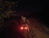
My plan was to install a LED Head Light, some sort of a tail light for others approaching from behind me at night or on the wooded trails. (The Dirt Bikers travel at very high speeds down the trails.)
I also wanted a way to charge my cell phone in case of a dead battery while in the Roaming Zones for hours at a time.
First things first, I source of power was needed. The engine is a HF Predator 212 a clone of the Honda GX200 series of engines. Parts interchange. A choice of one pair of coil ( Charging) or heavy duty two coils ( Lighting)are offered. Charging provides 30 Watts, Lighting 50 Watts or even a little more.
A three magnet flywheel would be needed as well.
The two coils will provide 4.1 amps just by themselves. For today's LED lamps that's a lot to play with
To boost the current ( Amps) a little, if need be, a small battery pack would be ideal. Also I wanted to run my cell phone charger
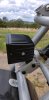
Now where to put all the things needed to build this system? Under the bikes phony gas tank.
Today's electronics are very small and powerful and best of all cheap to buy!
I then needed to find all the components to build the system. On line shopping sites will have all the parts you need. Do shop around for the best deals and lowest or free shipping. A little computer time can save you a lot of money. If your willing to wait for out of country shipping to show up, you can save even more.
So first things first, the Flywheel and Coils. There are real expensive and total junk. Read reviews and decide which ones you want. Make sure the parts will fit your engine. Some will not fit the HF Hemi engine.
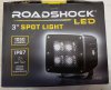
Next is the head light. I found the brand new LED Spot Light from
Harbor Freight was perfect, small, powerful and built like a tank out of cast aluminum. With a coupon it is dirt cheap. ( under 20 bucks)
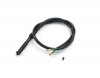
Next the tail light(s) were needed. I found two flashing Red LED lights that were made out of machined aluminum and shatter proof glass with all wiring and flasher module for 3 bucks shipped!
And boy are they bright!
Both head light and tail lights together draw less than 4½ Amps! That still keeps some Amps from the engine to play with without touching the current capability from the battery pack!
I made my battery pack by using batteries out of a laptop computer. The computer battery contained ten
18650 3.7 volt Li/Ion batteries. One was bad, the other nine were like new. These batteries carry a lot of current for their size, that is why they work so well in laptop computers.
A battery pack holder for these batteries is inexpensive and made well. I’m using a four cell holder with the he reason for this later on in this article. That being said, if your going to rough-it with your bike you should solder the batteries together.
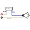
Now for the voltages that are generated and rectified/ regulated by the bikes alternator and on board battery pack.
The stator of the engine ( the new flywheel and coils) produces AC voltage. This voltage will vary from about 5 volt at slow idle to over 22 volts at max speed. Even with a head light bulb rated for AC this is either too low or way too much voltage.
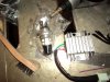
This voltage needs to be rectified through a full wave rectifier to a DC voltage. Since you cannot get ‘sometin fot nutin’ you will loose about 2 volts during the conversion to DC. You can do a ½ wave rectifier but the pulsating voltage is hard on LED’s.
The other half of the rectifier regulator is just that, a regulator. This device is set by electronics when the engine stator and battery pack is under full load ( Amps). If your running a 12 volt DC lighting system you want want the output voltage to 13.5 VDC. This will not only allow the light to run at its brightest it will also top off the battery pack and not overcharge it with all that extra voltage being generated as the engine speeds up. You really need a Rectifier/Regulator device if you want your lights and what ever else you power to last a long time.
You want to use wires that will carry your max load and not heat up and melt. For 99% of a head light and tail lights using a battery pack with stator 18 to 16 gauge wire will be large enough. If you’d like,14 gauge would give you more current carrying capability than you will probably will ever need.
You need a fuse that is 20% larger than your max load. ie, your drawing 3 Amps of current, use a 5 Amp fuse. Many small engine electrical systems will surge a little as a load is placed on them. This is hard on a standard fuse. A slow-blow fuse really helps prevent the fuse from failing during the surge.
Don’t throw in a large fuse, If your system is only capable of producing 5 Amps, putting a 10 Amp fuse is asking for trouble. The components will fail before the fuse blows.
Many In-Line fuse holders are weather resistant.
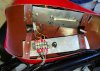
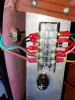
I’m a big fan of weather resistant Terminal Strips. By using these you terminate the wires using a Ring connector ( for vibration and minor shock/pulls) and you clearly can see which wire is on which screw terminal. This is a much better way to organize your wiring and looks a lot better than Wire Nuts or globs of electrical tape.
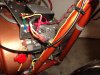
Since the bike is run outside all year long, I also place the wiring inside of Split Wiring Loom plastic wiring conduit. They come in colors if you want. HF has it in ten foot rolls for cheap.
The lights are controlled by a handlebar switch. The switch is rated for three times more current than my lights draw. You can use a relay to allow the current to go through it rather than the switch. But relays require current to turn on and stay on. Solid state relays require less current but they must be DC voltage rated in order to work properly.
I prefer a “Kill-Switch” to turn on/off the voltage from the R/R and the battery pack. This will keep the battery from draining while the bike is parked in the garage.
The switch is rated for current above the max load by 50% or more. This way it should never fail in use.
I hide the switch under the phony gas tank,but easy to turn on even wearing gloves.
You will most likely have electrical splices to make. If you do use Butt-Splices or other automotive connectors to help protect the exposed wire ends from the elements. I seal all my connections,once they have been tested, with hot melt glue.
Keep your connections away from water and mud if at all possible. Same goes for high temperatures touching the wiring.
As I have written, I’m hiding my electronic components under my phony gas tank. You may not have one. But you do have a seat, and in most cases an area in front,at the bottom of your engine you can store your electronics. A plastic or metal container is all you need. Many types and sizes are available on the www.
Your bike will produce many different frequencies of vibrations. Because of this I only recommend Ring Terminals. Don’t be lazy/cheap/could careless and just use bare wires tapped together or under a screw head. They will shake loose. Taped wire nuts can be used but look like crap,they trap water and dirt and will cause the wires to corroded and fail.
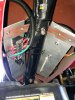
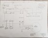
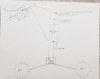
I an including photo’s of my lay out and will describe the point-to-point wiring. Keep it simple and well marked or written down for later spireas. Cell phone photos are a god send.
At the time of this writing I have put over 25 miles off road on the electrical system with the lights running at all times the engine is. So far no problems on the trail.
One component I mentioned as good to use in an earlier post turned out to be crap. I went with a much heavier duty device as listed in the parts breakdown.
end Part 1
It was inexpensive,will last a very long time and is extremely bright. The lights do not very in intensity with engine speed.
Let there be light...head and tail light that is….
I wanted to electrify my AM Hawg Ty minibike and gathered together a few things to make it work as I wanted it to.
My plan was to install a LED Head Light, some sort of a tail light for others approaching from behind me at night or on the wooded trails. (The Dirt Bikers travel at very high speeds down the trails.)
I also wanted a way to charge my cell phone in case of a dead battery while in the Roaming Zones for hours at a time.
First things first, I source of power was needed. The engine is a HF Predator 212 a clone of the Honda GX200 series of engines. Parts interchange. A choice of one pair of coil ( Charging) or heavy duty two coils ( Lighting)are offered. Charging provides 30 Watts, Lighting 50 Watts or even a little more.
A three magnet flywheel would be needed as well.
The two coils will provide 4.1 amps just by themselves. For today's LED lamps that's a lot to play with
To boost the current ( Amps) a little, if need be, a small battery pack would be ideal. Also I wanted to run my cell phone charger
Now where to put all the things needed to build this system? Under the bikes phony gas tank.
Today's electronics are very small and powerful and best of all cheap to buy!
I then needed to find all the components to build the system. On line shopping sites will have all the parts you need. Do shop around for the best deals and lowest or free shipping. A little computer time can save you a lot of money. If your willing to wait for out of country shipping to show up, you can save even more.
So first things first, the Flywheel and Coils. There are real expensive and total junk. Read reviews and decide which ones you want. Make sure the parts will fit your engine. Some will not fit the HF Hemi engine.
Next is the head light. I found the brand new LED Spot Light from
Harbor Freight was perfect, small, powerful and built like a tank out of cast aluminum. With a coupon it is dirt cheap. ( under 20 bucks)
Next the tail light(s) were needed. I found two flashing Red LED lights that were made out of machined aluminum and shatter proof glass with all wiring and flasher module for 3 bucks shipped!
And boy are they bright!
Both head light and tail lights together draw less than 4½ Amps! That still keeps some Amps from the engine to play with without touching the current capability from the battery pack!
I made my battery pack by using batteries out of a laptop computer. The computer battery contained ten
18650 3.7 volt Li/Ion batteries. One was bad, the other nine were like new. These batteries carry a lot of current for their size, that is why they work so well in laptop computers.
A battery pack holder for these batteries is inexpensive and made well. I’m using a four cell holder with the he reason for this later on in this article. That being said, if your going to rough-it with your bike you should solder the batteries together.
Now for the voltages that are generated and rectified/ regulated by the bikes alternator and on board battery pack.
The stator of the engine ( the new flywheel and coils) produces AC voltage. This voltage will vary from about 5 volt at slow idle to over 22 volts at max speed. Even with a head light bulb rated for AC this is either too low or way too much voltage.
This voltage needs to be rectified through a full wave rectifier to a DC voltage. Since you cannot get ‘sometin fot nutin’ you will loose about 2 volts during the conversion to DC. You can do a ½ wave rectifier but the pulsating voltage is hard on LED’s.
The other half of the rectifier regulator is just that, a regulator. This device is set by electronics when the engine stator and battery pack is under full load ( Amps). If your running a 12 volt DC lighting system you want want the output voltage to 13.5 VDC. This will not only allow the light to run at its brightest it will also top off the battery pack and not overcharge it with all that extra voltage being generated as the engine speeds up. You really need a Rectifier/Regulator device if you want your lights and what ever else you power to last a long time.
You want to use wires that will carry your max load and not heat up and melt. For 99% of a head light and tail lights using a battery pack with stator 18 to 16 gauge wire will be large enough. If you’d like,14 gauge would give you more current carrying capability than you will probably will ever need.
You need a fuse that is 20% larger than your max load. ie, your drawing 3 Amps of current, use a 5 Amp fuse. Many small engine electrical systems will surge a little as a load is placed on them. This is hard on a standard fuse. A slow-blow fuse really helps prevent the fuse from failing during the surge.
Don’t throw in a large fuse, If your system is only capable of producing 5 Amps, putting a 10 Amp fuse is asking for trouble. The components will fail before the fuse blows.
Many In-Line fuse holders are weather resistant.
I’m a big fan of weather resistant Terminal Strips. By using these you terminate the wires using a Ring connector ( for vibration and minor shock/pulls) and you clearly can see which wire is on which screw terminal. This is a much better way to organize your wiring and looks a lot better than Wire Nuts or globs of electrical tape.
Since the bike is run outside all year long, I also place the wiring inside of Split Wiring Loom plastic wiring conduit. They come in colors if you want. HF has it in ten foot rolls for cheap.
The lights are controlled by a handlebar switch. The switch is rated for three times more current than my lights draw. You can use a relay to allow the current to go through it rather than the switch. But relays require current to turn on and stay on. Solid state relays require less current but they must be DC voltage rated in order to work properly.
I prefer a “Kill-Switch” to turn on/off the voltage from the R/R and the battery pack. This will keep the battery from draining while the bike is parked in the garage.
The switch is rated for current above the max load by 50% or more. This way it should never fail in use.
I hide the switch under the phony gas tank,but easy to turn on even wearing gloves.
You will most likely have electrical splices to make. If you do use Butt-Splices or other automotive connectors to help protect the exposed wire ends from the elements. I seal all my connections,once they have been tested, with hot melt glue.
Keep your connections away from water and mud if at all possible. Same goes for high temperatures touching the wiring.
As I have written, I’m hiding my electronic components under my phony gas tank. You may not have one. But you do have a seat, and in most cases an area in front,at the bottom of your engine you can store your electronics. A plastic or metal container is all you need. Many types and sizes are available on the www.
Your bike will produce many different frequencies of vibrations. Because of this I only recommend Ring Terminals. Don’t be lazy/cheap/could careless and just use bare wires tapped together or under a screw head. They will shake loose. Taped wire nuts can be used but look like crap,they trap water and dirt and will cause the wires to corroded and fail.
I an including photo’s of my lay out and will describe the point-to-point wiring. Keep it simple and well marked or written down for later spireas. Cell phone photos are a god send.
At the time of this writing I have put over 25 miles off road on the electrical system with the lights running at all times the engine is. So far no problems on the trail.
One component I mentioned as good to use in an earlier post turned out to be crap. I went with a much heavier duty device as listed in the parts breakdown.
end Part 1