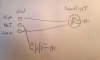
Alright all you electrical pros out there in minibike world, got one for you. I'm working on the harness for my mini chopper. This is a total loss system, no generator. I have the headlight working perfectly. The conundrum starts when I try to add the tail light. How do I wire it so the tail lights with both high and low beam? Yes, I know what happens when I jump a wire to both side of the switch!
Thanks in advance!
Thanks in advance!
Attachments
-
 3.1 MB Views: 36
Last edited:
")