Detailed Rebuild How-to: Briggs 3hp Cousins

#21
Last of the metal prep....Fuel Tanks

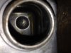
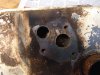
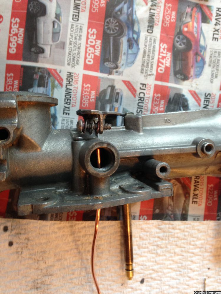
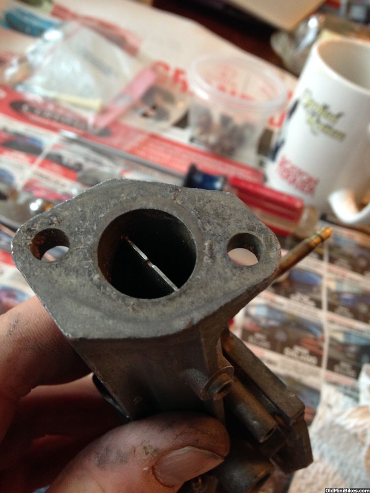
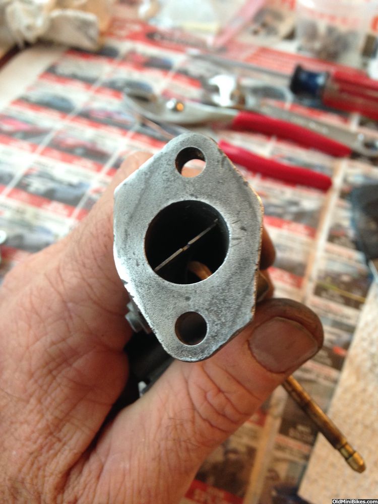
Finished up both tanks today. One of the tanks was in great shape on the inside and the other, well....not so much. I had picked both up off of eBay and I knew what I was getting. The not-so-hot tank was much older and had the back-in-the-day heavy baked enamel finish. The carb's fuel pick ups on this tank were filled with corroded junk but more on that later. The finished tanks are below:

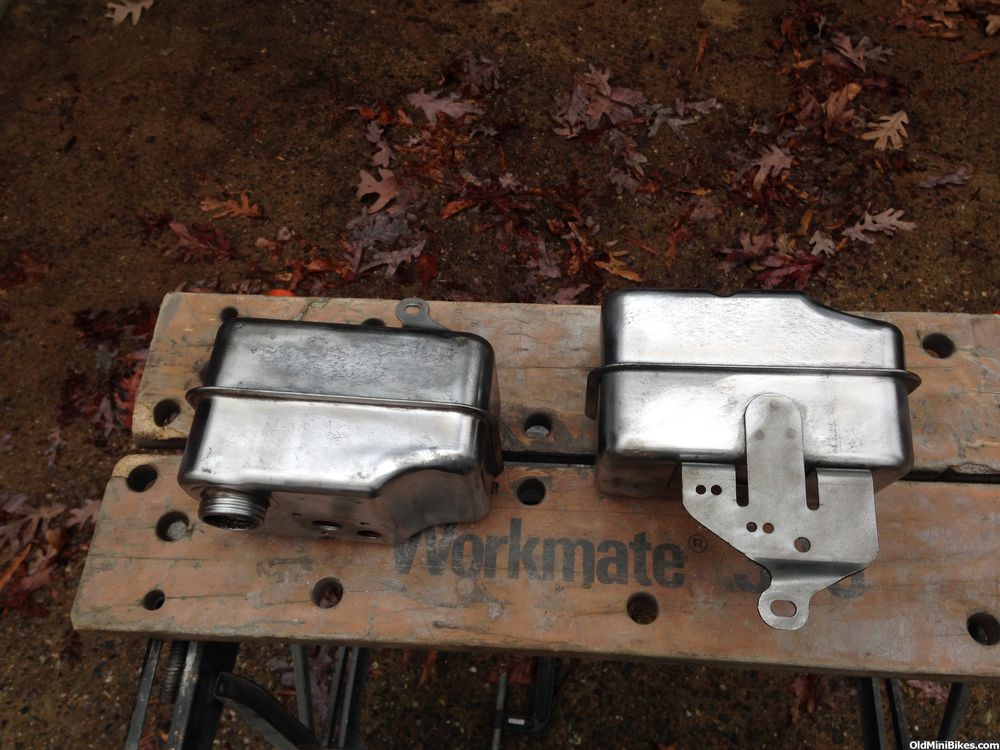
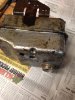
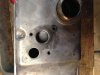
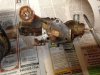
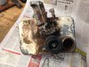
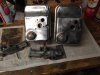
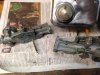
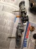
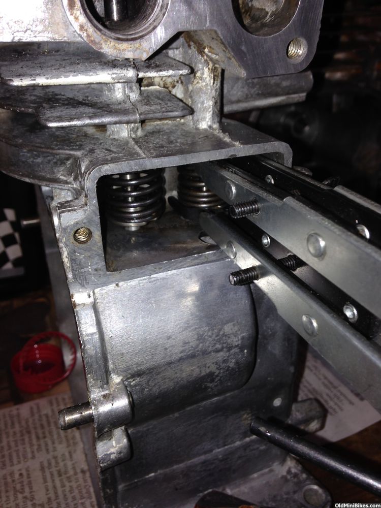
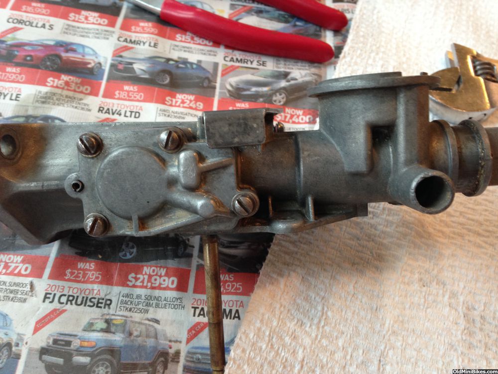
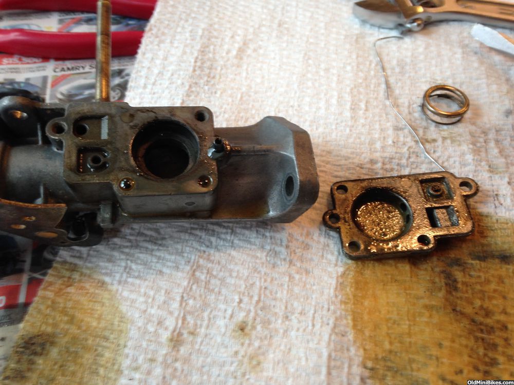
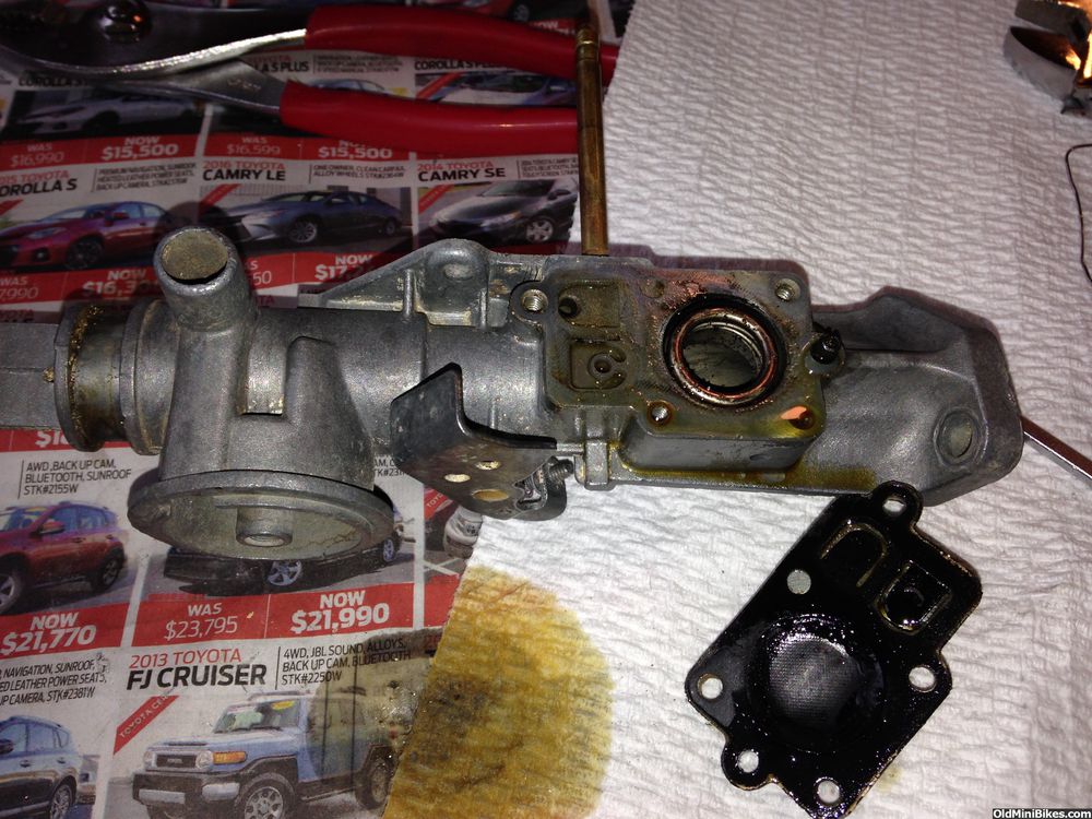
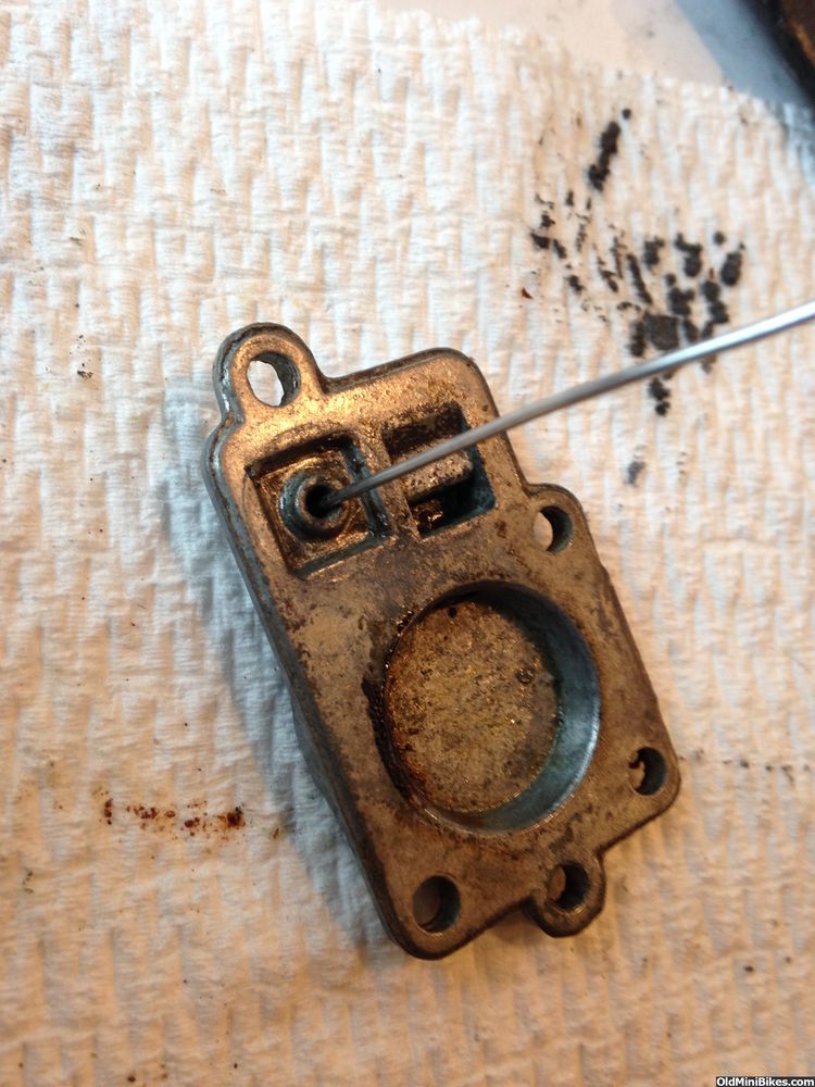
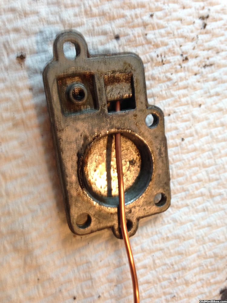
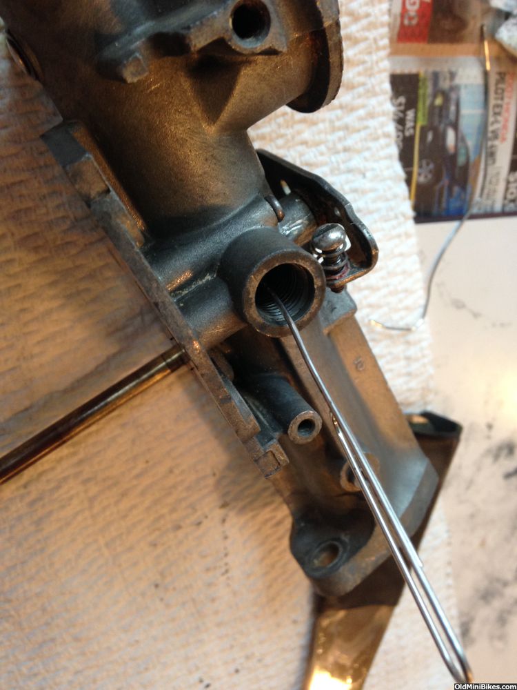
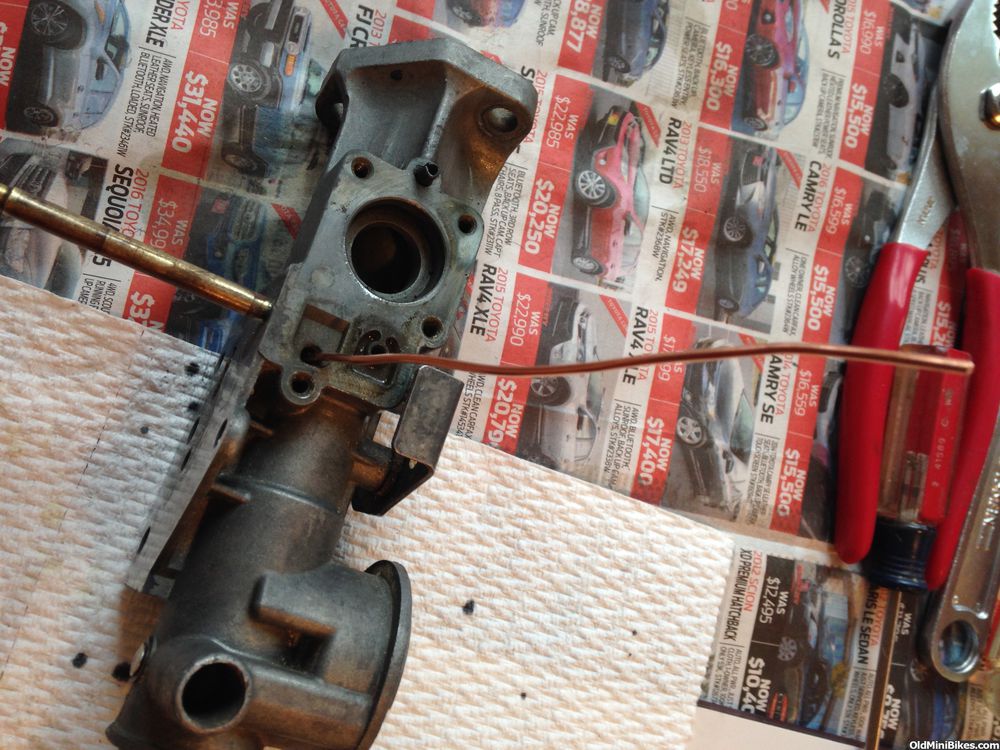
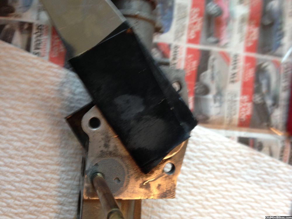
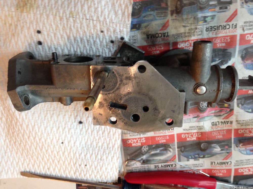
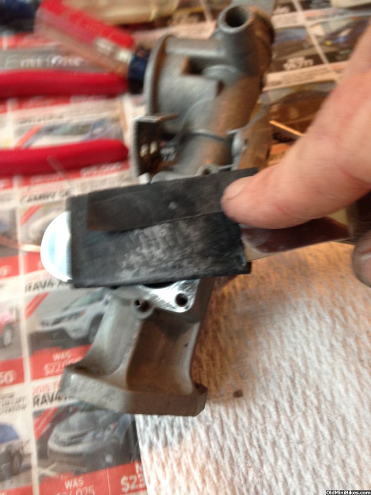
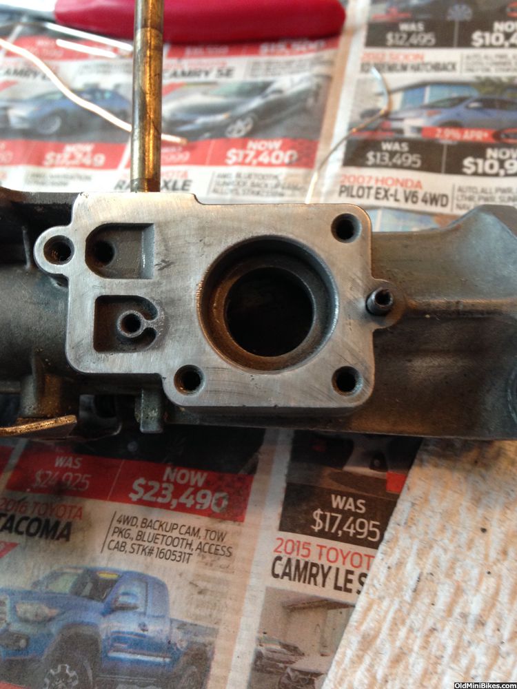
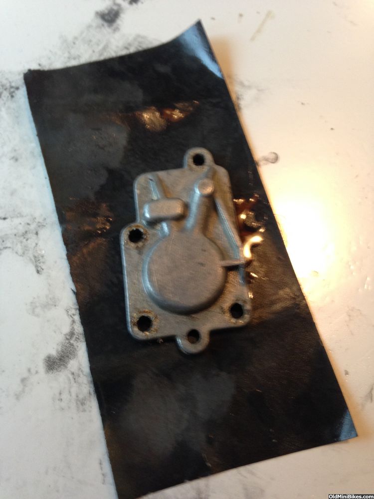
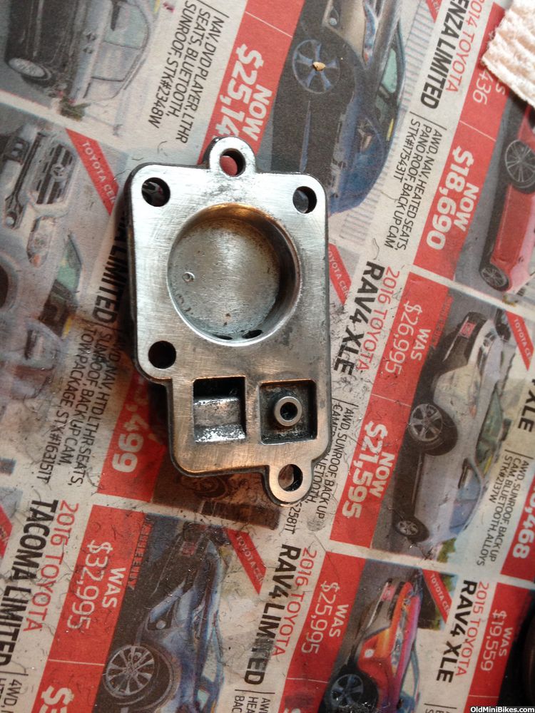
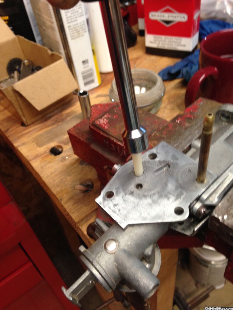
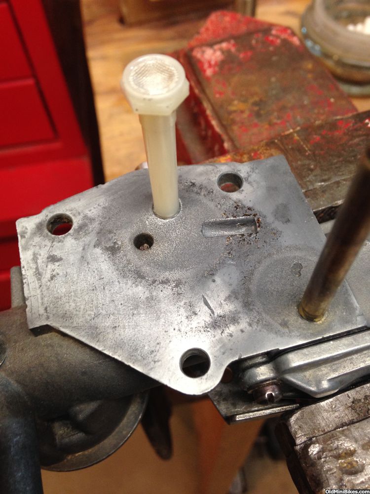
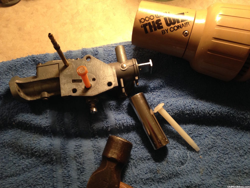
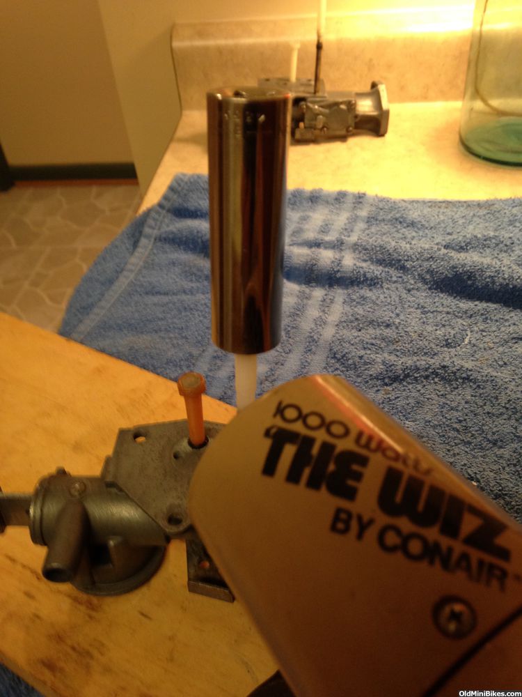
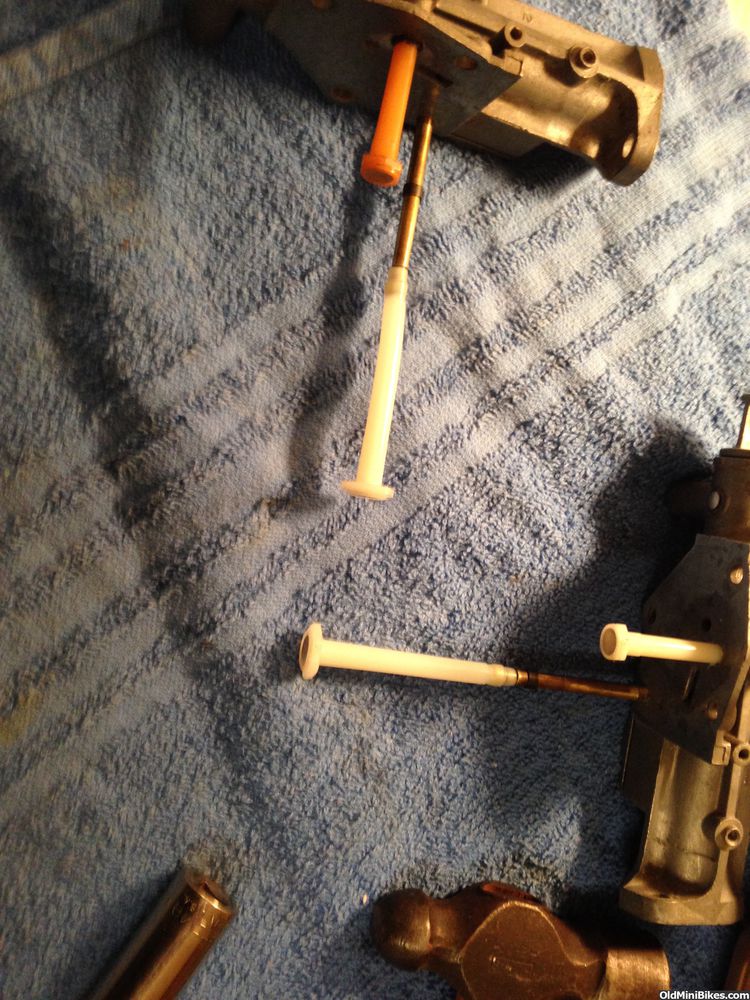
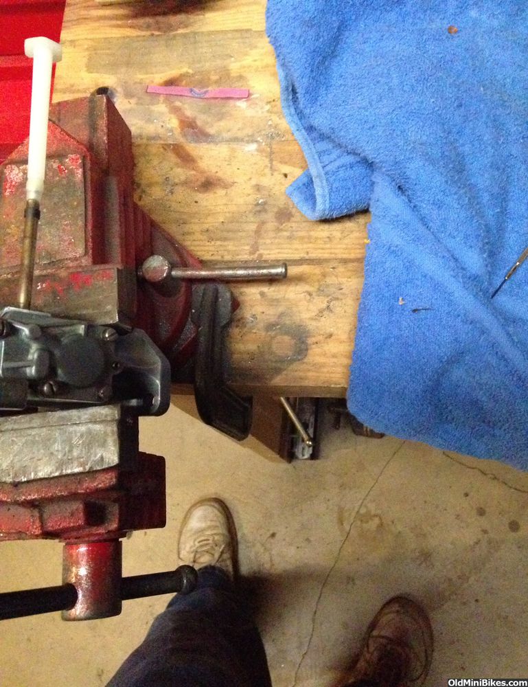
To get the tank clean on the inside, I used Rustoleum liquid rust remover and steel wool on a screw driver to swish it around on the surfaces. I let the goop sit for about 20 minutes and flushed the tank with warm water. Cleaned out pretty nicely yet there was still some rust. I put a couple of handfuls of pebbles in the tank, wrapped it in an old blanket and ran it in the dryer (with no heat!) for about 30 minutes. The carbs were degreased and stripped of paint and prepped for their rebuild.

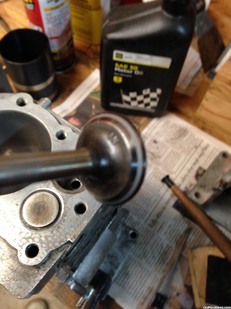
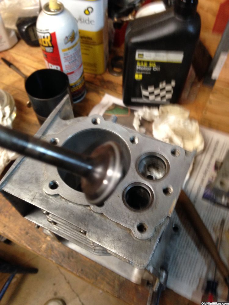
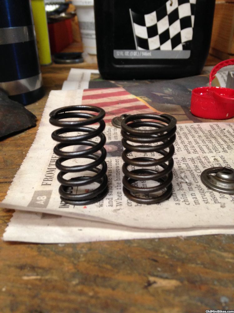
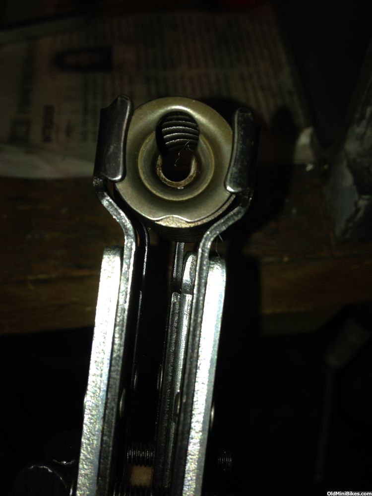
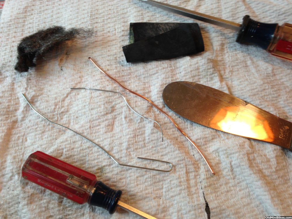
More pics of the work:
 

Attachments

#22
Ring Gap on the '64

On to the rebuild. The service manual says to NOT deglaze the Kool-Bore cylinder wall and it had no evidence of scoring. The cylinder got one final cleaning and lubed with a bit of oil. This table was used to determine if the existing rings were still good:


The Oil Ring measured at 0.023, so it was fine.


The Compression Rings both measured 0.021.


The side clearance on the piston could not exceed 0.006. All three rings were at 0.006 and the piston scored as serviceable.
 
#23
Valves on the '64

Cleaned up the valves little more, and made sure the guides were clear in the block. This diagram is helpful in understanding the valve seating process:


Use a fine grit compound when lapping in the valves. Both valves required minimal work to get them ready. Oil the valve stem before inserting in the guide during and after the lapping process. Make sure you remove all the grit when done.


Notice the valve springs are two different sizes. The taller spring is the exhaust side.


A valve spring compressor makes quick work. The first pic shows how the retainer should look in the compressor.
 
#27
"Blueprinting" the Carbs (Well, sorta)

Both carbs were rebuilt with Briggs overhaul kits. I did the same sorts of things to both carbs, so only one is covered and it was the nastier of the two--from the older white tank. The carb was seriously gunked up. This pic shows the various "tools" I used to attack the sludge:


The rest of the original white paint was picked off the body of the carb:


Then the fun began with disassembly (on the kitchen table while the other half was at the dentist)...and did it smell....:nuke:
 
Last edited:
#28
Gunk Removal

The original engine must have endured an early death (or rode hard and put up wet). The carb was full of gunk and assorted other debris. I used two different sizes of paper clips and 14g copper wire to get at the various ports/jets on the carb. The long supply tube was completely plugged and I had to work it out gently. The diaphragm was full of stuff and the two flappers were gunked up, too. All told, about an hour was spent carefully cleaning, poking and prodding to get everything clear. In between rounds of poking, I sprayed the carb with cleaner outside to remove the remains.

 
#29
Sorta...The Blueprinting

Air leaks are killer on Briggs engines with tank mounted carbs. Carb to tank, diaphragm cover or intake to block. There was a ton of corrosion on the tank mount and a build-up of residue on the intake surface. Often the diaphragm cover is not completely square, and this one was no exception.

Patience is required to complete this task. Go slow, so as to not make matters worse. To clean these surfaces up, steel wool and a screw driver were used to clean off the big stuff. A smooth glass cutting board served as a backer for 600 grit wet sandpaper. The diaphragm cover was worked until a fairly uniform surface appeared. Because there were obstructions, a small spatula was wrapped in 600 grit and the mating surface for the diaphragm cover was cleaned up. Same process was used on the tank mounting flange. You'll never get all the casting rash out, so the idea is get a decent uniform surface (If you take too much off, the efficiency of the vacuum pumping action is reduced making matters worse).

 
#32
Installing Fuel Pick-Ups for Briggs tank mounted carbs

This easily is the most frustrating task when rebuilding a Briggs tank mounted carb. Some have all nylon pick up tubes, some have a brass tube and a nylon pick up tube. You have to be careful when ordering new tubes as they come in different sizes....one for the shallow bowl in the tank and two (2) different sizes for the main tank depending on whether it's a 2 qt or 3 qt. The cousins have brass pipes leading to the main tank pick up. To remove the bad pick ups, gently clamp the intake runner side of the carb in a vise (stay away from the tank mount surface!!!!!) and use a small blade screwdriver to drive the ferrule off the nylon tube. The small tube should unscrew from the carb.

The shorter tube gets installed first. Use a nut driver to put even pressure on the tube as it cuts new threads in the nylon. The inside of the tube has a metal sleeve, so no worries. The manual says lots of pressure may be needed, and it's right. Screw it in until bottoming out.


The long pick up is another treat.:laugh: The manual suggests heating the tube in water before installing. NOPE.:no: Below are the tools needed to install the long pick up:


I saved my hair dryer from my late 70's disco days and use it in the shop.:doah:MAKE SURE YOU PUT THE NEW FERRULE ON THE TUBE FIRST.

The best way to install the new pick-up is to heat the brass tube AND the nylon at the same time (Press the end of the tube on the brass tube--it'll go 1/8" if you're lucky). You can't melt the nylon with a 1000 W hair dryer (well you could, but don't). Use a 9/16" deep socket to press the tube on (you can lightly tap with a hammer)...heat again, press some more...heat again........It'll go on, eventually...... Press to the groove in the brass tube.


On to the ferrules--You can make this too difficult. Simply place the carb back in the vise (stay away from the mounting flange) and snug it. With a small flat blade screwdriver, tap the ferrule over the nylon to where the groove stops.
And that's it.
BTW, I only have one shaggy hair disco photo, so don't ask.:eek:
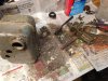
ut: It ain't pretty.
 
Last edited:
#33
Excellent write up Shop Teacher. I've had problems with the Pulsa pickups before and saw that kit and you pretty much answered every question I had on it. :thumbsup:
 
#34
Companion to Post #22 Guide to Rings and Their Profiles

I forgot to post this image from the manual about the various ring profiles. There is a correct order to install the rings. The oiler is obvious and fits closest to the skirt and may have an inner expander. If you are removing rings to check gap, make sure you keep them in order: Upper, Middle, Oiler. Reinstall the rings (lubed up) with the correct edge up and in accordance with the guide that often comes with new rings.


And this is what happens when you're not careful pulling the rings off the piston::blink:

I had another set.....:rolleyes:
 
#35
Valves on the '74

Not going into a lot of detail here, as it's been covered in post #23. The intake valve was in pretty good shape and needed just a tad of lapping to even up the face. The exhaust valve must have been sticking a bit on this engine (I have a good idea why, but that's a little later). Lots of carbon build up, so much that the face was completely caked. Cleaned it up with steel wool, Blaster, and a soft wire wheel in the drill press. Even with the cleaning, the face was still pretty nasty. Normally, you WOULD NOT use a coarse compound to lap the valves. This valve needed a bit more TLC, so a coarse compound was used to start the cut. Once I started the beginnings of a line, I switched to the fine compound. Remember to clean the valves and guides with brake or carb cleaner.

 
Last edited:
#36
Installing the Piston and Crankshaft on the '74

Valve installation was the same as on the '64 (post 23). The cylinder bore was cleaned and lubed with 30 wgt oil. The crankshaft was cleaned similarly. I used a soft wire wheel to remove any surface rust on the exposed ends of the crank (flywheel and PTO).

When the piston is installed, make sure the skirt is well lubed and the ring gaps are spaced equally around the piston. There are ways to install the piston without using a ring compressor, but I don't recommend them. The crank needs to be inserted before the piston is inserted in the cylinder.
Tighten the Ring Compressor until the rings disappear. Use the butt end of a hammer or mallet to gently tap the piston down. Resistance means you still have a ring not fully compressed--STOP, if you do or risk breaking a ring.
Once in place, install the rod cap paying attention to the "crack" line of the rod--caps fit on ONE WAY only. The dipper is installed (and only fits in one spot). On top goes the locking tab (older models will have this).


Torque the rod bolts to 100 in-lbs.


Using a screwdriver and a hammer, bend the locking tabs up on both rod bolts to lock the rod bolts.


Cover is next....
 
Top