tecumseh engine kill switch question

#1
20220310_112854.jpg 20220405_154204.jpg
Hi Guys,
I'm in the middle of a speedway mini bike project. The bike didn't have a kill switch, so I've added a simple push button 2 wire handle bar mount switch. My question is, three wires are already coming out of the flywheel area(in a bundle). There is a red, green, and black. Can I attach 1 kill switch wire to a frame ground, and the other to the black wire coming out of this group? I'll try and add the picture. Thanks for any help.
 

mustangfrank

Well-Known Member
#2
View attachment 288446 View attachment 288447
Hi Guys,
I'm in the middle of a speedway mini bike project. The bike didn't have a kill switch, so I've added a simple push button 2 wire handle bar mount switch. My question is, three wires are already coming out of the flywheel area(in a bundle). There is a red, green, and black. Can I attach 1 kill switch wire to a frame ground, and the other to the black wire coming out of this group? I'll try and add the picture. Thanks for any help.
The green wire should be your ignition kill switch wire, the black and red are the power outputs (- and +).
 
Last edited:
#6
Yes it is AC, never said otherwise, technically, but not the point of the thread. Green is still the ignition kill, black is still ground or (-) and red is still power/hot or (+).
You stated they were positive and negative. That means DC. Black is not "ground" it is another AC lead, just like the red one. There are two separate AC leads. You were correct in pointing out that the green was ignition grounding wire for kill switch. But there are no negative and positive leads on the AC system. What you circled on the diagram has nothing to do with the 610981. You suck. Just kidding. No one likes to have their errors pointed out. But hey, as you said, you did answer the question at hand correctly.
 

mustangfrank

Well-Known Member
#7
You stated they were positive and negative. That means DC. Black is not "ground" it is another AC lead, just like the red one. There are two separate AC leads. You were correct in pointing out that the green was ignition grounding wire for kill switch. But there are no negative and positive leads on the AC system. What you circled on the diagram has nothing to do with the 610981. You suck. Just kidding. No one likes to have their errors pointed out. But hey, as you said, you did answer the question at hand correctly.
I do believe the wire color code diagram (bottom) is used for every alternator on the page as a key, note that all colors described aren't on every alt diagram. I gotta go check my pile of alts, I might of been thinking of a DC or older AC unit with a brown (-).
 
Last edited:
#8
Yes it is AC, never said otherwise, technically, but not the point of the thread. Green is still the ignition kill, black is still ground or (-) and red is still power/hot or (+).
Black is not ground..

You stated they were positive and negative. That means DC. Black is not "ground" it is another AC lead, just like the red one. There are two separate AC leads. You were correct in pointing out that the green was ignition grounding wire for kill switch. But there are no negative and positive leads on the AC system. What you circled on the diagram has nothing to do with the 610981.... No one likes to have their errors pointed out.
For the record I was not trying to point out anyone's errors, just trying to steer the OP in the right direction with the correct diagram of his alternator. Might be helpful if it were a sticky as this question comes up fairly frequently.

I do believe the wire color code diagram (bottom) is used for every alternator on the page as a key.
Again, I have to (respectfully) disagree. Black on the OPs alt is not ground, it is another AC output. If the OP connects black to ground they are sure to fry their coil.
 
#9
I do appreciate the help. So, the final answer is one new kill switch wire to the green wire coming off the engine, the second kill switch wire gets connected directly to the frame somewhere? Attaching the two kill switch wires directly to the green and black wires coming off the engine will fry the coil. I bet this does come up a lot.
 
#10
I do appreciate the help. So, the final answer is one new kill switch wire to the green wire coming off the engine, the second kill switch wire gets connected directly to the frame somewhere? Attaching the two kill switch wires directly to the green and black wires coming off the engine will fry the coil. I bet this does come up a lot.
YES!

FYI- those push button switches that clamp to your handlebars with one wire make a lot cleaner installation. In that application, the switch body itself is the ground.

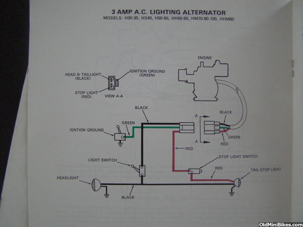
The black wire is AC
The red wire is AC

Both of these are separate and out of phase. One powers lights for example, the other powers the brake light, or whatever combo makes one happy.

(If they were phased together from a frequency standpoint, ie providing the same voltage at the same time, positive, or negative, they would explode spectacularly) (referred to as paralleling alternators, and something electrical engineers have to provide safeguards against in multi-generator realms via frequency sensing devices.

Not a problem on these, since the actual coils going to the black and the red wire, or later on, yellow wires, are physically separated, which is plain to see when you look at them. (think rotation as setting up frequency)

As alternators, they go from a maximum of negative 12 volts AC to positive 12 volts AC at whatever frequency the engine RPM is at. This is why systems equipped with a battery need to have diodes. (Rectifiers) They bias the output voltage, preventing it from allowing negative voltage, (voltage below zero) to pass. This provides what some call "DC" to charge the battery. However, it is not really DC, it is pulsating DC, running from low voltage to max. voltage at the frequency set up via RPM.

There is no such thing on this alternator as "alternator DC (+) lead, or "alternator ground/battery ground." There is no DC anywhere. There are no grounds associated with the alternator outside of the fact that it's electrical potential is referenced to the frame. (AC power)

When you ground the green wire, you are in essence shorting the points to ground, which completely removes voltage potential from the field, thus collapsing it, and preventing spark from occurring via the primary coil.

So no, it's not verbal salad to someone who has an understanding of electrical theory, and quite honestly beyond the scope of your question. This exact topic however has been discussed here, and at least a few members from long ago have attempted to build electronic versions of controlling as well as using primary ignition coils to generate.

Oh and....I'm pretty sure the "black" is what used to be the "brown" on older models.
 

mustangfrank

Well-Known Member
#11
Yes, follow above, not me, I was wrong to say ground! Sorry for any confusion, I was incorrectly mixing up my practical knowledge with the book color key, my last wiring job was a DC alt/coil to a battery system.
 
Last edited:
#12
Yes, follow above, not me, I was wrong! Sorry for any confusion, I was incorrectly mixing up my practical knowledge with the book color key, my last wiring job was a DC alt/coil to a battery system.
Thank you Frank. My joking about "you suck" was because of Mark's "terse" reply with the schematic. A dry bit of humor. Like you, my mind sees black in an automotive setting and thinks "ground this."

I've been wrong about as many times as I've been right- on this forum, and had to come clean several times, like that stupid rattle sound in a Tecumseh carburetor and what it means.
 
Top