Open Class: drbhuntnfish 2x2 hydrostatic minibaja

#61
Hey man, sorry about your gas tank, Stangrcr1. Though it looks like your fix is gonna work out to be better than the original. Nice job!

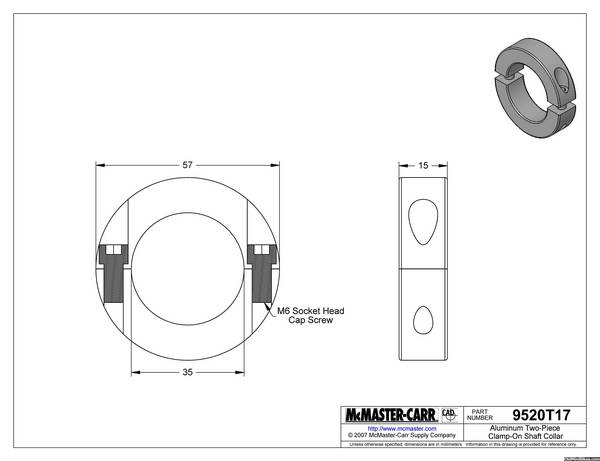
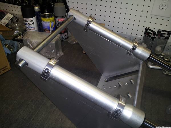
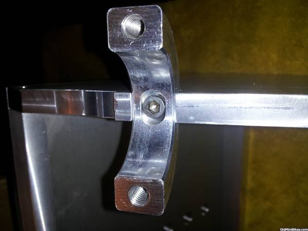
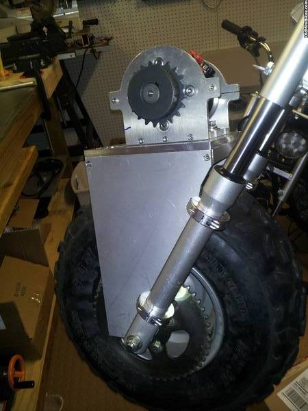
You are almost right about the truss, but the screws don't carry any vertical load, because the top inside flat on the 4 notches in the truss rest on the top flat of the 4 clamps. Sideways, like if I kicked it from the side, the 4 bolts do carry the load in single shear.

I calculated the shear strength of one 10-32 Stainless Steel screws (.1508" min diameter) to be about 750 lbf, so if I hit it from the side two might let go at around 1500 lbf.

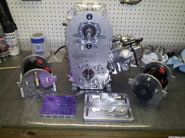
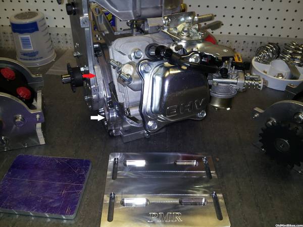
My orignal plan was to get everything tight and installed in place, and have a welder friend TIG the sides where the outside vertical face of clamps meet the vertical part of the notches where they touch. But my welder friend said that his welder is not powerful enough to TIG 3/8" thk aluminum. :doah:

Do you think these parts can be welded if I can get a pro-shop to do it? The clamps are also aluimnum.


Darrel
 
Last edited:
#62
Sure, they can be welded, but unless the clamps are double split, you won't be getting the truss off. Also, as I mentioned earlier, the welding may change the clamp strength.

Do you have pics of said clamps?
 
#63
Yep! Here 'tiz... Two piece. The truss comes into the collar perpendicular to the split, and the heads of the collar screws will point to the rear of the bike. So in the sketch below, the top half comes off, the lower half is screwed to the truss. I'd like to weld this bottom half into the notches of the truss after everything is aligned.

 
#64
Just drill a hole through inline with the other bolts, throught the forks also and "pin" it in. Like a 1/4-20 bolt. With the clamping and then pinning it... it aint goin anywhere. My thought.:wink:
 
#65
Okay then. I say tack it in place and full weld it both sides with it removed from the forks. Also, if the holes are threaded all the way through, I would put longer bolts so they engage more thread in the "bottom" halves.

I still think I would add a third collar.....

I tend to overbuild things to where it would take an act of God to break them. While I understand building to the limit of the available strength, I would rather have insurance.

Since this is all aluminum, what about just pulling the guts out of the forks and welding the truss direct?
 
#66
How about bolting it all up, and then welding the back half of the collars
to the forks and weld the front half of the collars to the truss?
Then it could still be disassembled but would be solid as hell.
 
#67
March Update

Well, just reporting in with a few photos:
Most of the work this month doesn't really show up as progress, but milestones begin as inchstones, I suppose. The photo shows the engine and pump mounted together along with the front and rear wheel motors, and the engine mounting plates:


What you can't see in the above picture is the 1/2" aluminum spacer I had to add between the engine and the pump mounting plate (old tav2 mounting plate), which I found necessary in order to space the pump over so that the pump main inlet and outlet, and the charge pump outlet are not blocked by the top of the frame. As shown below, I replaced the cast engine side plate cover with a ARC billet cover (white arrow) to create a more solid mount for the pump, and added the aluminum spacer (red arrow) to move the pump over relative to the bike frame.


Last edited:
#68
Here's a photo of the top of the hydraulic pump in just sitting in the frame, looking down from above-


As shown above, now both the pump inlet and outlet are uncovered, and the charge pump outlet is also uncovered, while the engine now can be bolted onto the bike's mounting plate. Before adding the 1/2" spacer, the engine was too far over to to the left side.


It's a tight squeeze, but the engine and the pump, and the rear wheel motor now fit in the frame with about a 1/4" to spare between the top of the pump and the bottom of the frame:


Tomorrow, I plan to drill new mounting holes and bolt these components in place. I'm still waiting for the front wheel truss to come back from the machine shop, which should be any day now. Then I can start some re-assembly.
DRB
 
Last edited:
#71
Update - I finally got the front truss back from the machine shop, and it fits great...


To keep the truss from sliding down the front forks if the clamps come loose, I decided to sleeve the bottom of the forks with some aluminum tubing which was cut at 2.75" in length. These were 'shaped' on one end to make them oval by squeezing them in a vice. Then I 'massaged' them onto the fork ends with a BFH and a block of wood. I was a little apprehensive, but it worked out great. The sleeves are trapped by the tight fit and the axle going through them, and the bottom clamps on each side of the truss rests on the sleeves. Here are a series of photos that show what I did:

Sleeves in the background:


Ovaling the bottom of the tube:


One down, one to go:


Done...


Truss mounted on forks:


I added a little bit of adjustment in the clamps by having an oval hole and oval c'bore machined into each clamp.
That helped to ease any misalignment issues between the truss and the forks, as the truss is extremely rigid.


Here's the sprocket side of the truss... I tried to rotate this view, and thought I had it, but it still comes out like I imported in. (Can someone explain to me how to get this right???)


That's all I have for now - the next three steps have been the hardest for me to figure out... How to mount the manifold for the hydraulics, how to mount the gas tank, and how to build and mount the reservoir for the hydraulic fluid.

Thanks all for your kind comments and support!
Darrel
 
Last edited:
#73
Thanks, Buckeye! I didn't report on the size of the tubing that I bought... So let me see if I can find that info...

I bought it from Online Metals...

2024-T3 ALUMINUM TUBE
1.5" OD X 0.049" 2024-T3 Bare Drawn Aluminum Tube
Random Length (10"-12")

the bottoms of the forks where the axle goes through have raised seats on them that keeps the axle head and the nut, and the wheel fully in contact with the forks. In order to get the tubing to move over these seats, I had to file the edges of the seats down where they contacted the edge of the tubing. When the axle is tightenened on the wheel, new seats are formed as the tubing is compressed on either side of the forks. I didn't want to file the seats at all, but it was the only way to get the sleeves to slide over. I should add that not all of the seat was filed away, just the 'sides' of the seats where the interference was. Hope that is clear. I was 'into it' and forgot to snap a pic while I was filing, and hammering, and praying :smile:

DRB
 
#75
WOW! that is nice!....How about some artistic lightening holes cut in the side panels of the mount?....:thumbsup:Looking great!:thumbsup:....Scootercat....
 
#78
Whew! Taxes away tonight:) But a sad day for the country- several friends of mine from Austin are in Boston for the marathon.

I have been gathering parts to make a final dash to the finish with my 2x2 bike - but no progress to show off.

Hope you all are safe. I'll be back at the build over the next few days.

Cheers!
Darrel
 
#79
It's officially a roller!!!:laugh:


I had a lot of help today from my new friends Bob and Michael at the local hydraulic hose and supply shop; Michael was kind enough to come in on a Saturday when the shop is normally closed and help me through fitting and installing the hydraulic hoses.

Just a few big things left - finding room and fitting both a gas tank and a hydraulic oil reservoir, hooking up the control cables, and installing the drive chains. It's gonna be close!

drb
 
Last edited:
Top